Check patentability & draft patents in minutes with Patsnap Eureka AI!

Touch position detection method

A detection method and touch position technology, applied in the fields of instrumentation, electrical digital data processing, data processing input/output process, etc.

Inactive Publication Date: 2013-01-16
SILICON INTEGRATED SYSTEMS
View PDF3 Cites 0 Cited by
  • Summary
  • Abstract
  • Description
  • Claims
  • Application Information

AI Technical Summary

Problems solved by technology

However, because of various interfering signals, misjudgment can easily occur

Method used


Image

  • Touch position detection method
  • Touch position detection method
  • Touch position detection method

Examples


Embodiment Construction

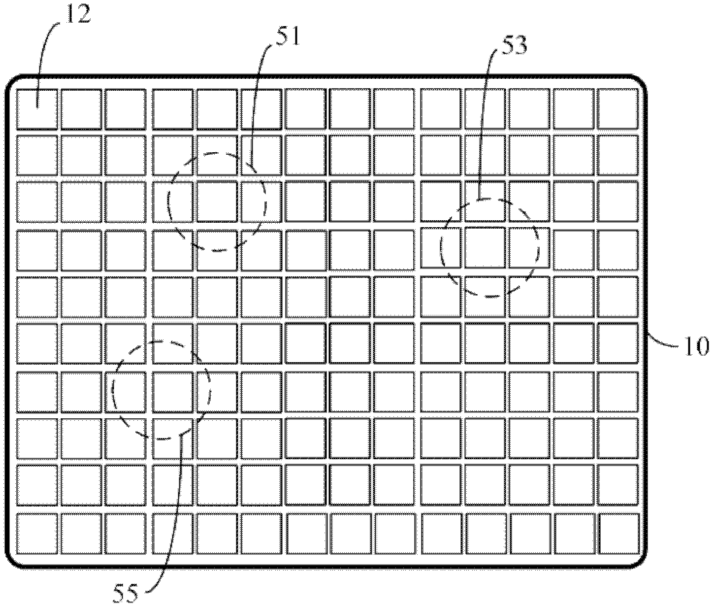
[0027] figure 1 It is a schematic diagram showing a touch on the touch screen 10 . The touchscreen 10 has a matrix of dots 12 . In this embodiment, it is assumed that three positions 51 , 53 , 55 are touched, marked with dotted circles, as shown in the figure.

[0028] After scanning and detecting all the points 12 on the touch screen 10 , a detection circuit (not shown in the figure) determines that some points have significant changes (eg capacitance changes). Points with a significant change are referred to here as valid detection points 22 to be distinguished from points 12 that do not have a sufficiently large change. figure 2 It is a schematic diagram showing effective detection points 22 on the touch screen 10 . In the figure, valid detection points 22 are indicated by filled hatching. However, as mentioned above, some valid detection points 22 may not actually be touched due to the presence of interference signals.

[0029] In one embodiment of the invention, eac...


PUM


Abstract

The invention discloses a touch position detection method for a touch screen. The method comprises the following steps: comparing a detection value of a specific point and a first threshold value and comparing the summation of the detection values of a group of points comprising the specific point and a second threshold value, and detecting the values; and moreover, checking the detection value of the specific point so as to judge whether the detection value is the maximum value in the group of points. With the adoption of the method, the detection accuracy of a touch position can be improved.

Description

technical field [0001] The invention relates to a touch detection method, in particular to a method for accurately detecting and determining a touch position on a touch screen. Background technique [0002] Nowadays, touch detection devices are widely used in various industries, and touch screens including touch panels are very popular. [0003] In the prior art, touch screens have a matrix of dots on the screen to receive a single touch or multiple touches from a finger or other suitable object. The detection circuit detects data from these points and determines which point or points are touched. [0004] In order to achieve various functions, one or more touch locations on the touch screen need to be accurately detected. However, misjudgment can easily occur because of various interfering signals. [0005] Therefore, there is a need for a solution to accurately detect the touch position on a device such as a touch screen. Contents of the invention [0006] The purpos...

Claims


Application Information

Patent Timeline
IPC IPC(8): G06F3/041
Inventor 郭锦华徐日明
Owner SILICON INTEGRATED SYSTEMS
Features
  • R&D
  • Intellectual Property
  • Life Sciences
  • Materials
  • Tech Scout
  • Unparalleled Data Quality
  • Higher Quality Content
  • 60% Fewer Hallucinations
Learn More