Electric field coupling-based wireless power transmission system

A technology of wireless power transmission and electric field coupling, applied in the field of wireless power transmission systems based on electric field coupling, can solve problems such as no better solution, changes in system structure parameters, and unstable working states of the system, so as to improve transmission capacity and transmission. efficiency, reducing electromagnetic interference problems, and improving system performance

Active Publication Date: 2013-01-16
重庆华创智能科技研究院有限公司
View PDF4 Cites 69 Cited by
  • Summary
  • Abstract
  • Description
  • Claims
  • Application Information

AI Technical Summary

Problems solved by technology

However, in ICPT technology, the problem of electromagnetic interference and the blocking of energy transmission by metal obstacles have always been the key issues affecting the further development of ICPT technology.
[0006] However, in the existing ECPT system applications, since the coupling plate is usually a separate structure, the transmission distance may change under different coupling states during the working process, which will cause changes in the system structural parameters, resulting in a decrease in the power transmission capacity of the system. and transmission efficiency drop, and even the system will be in an unstable working state
A comprehensive analysis of existing patents and literature shows that there is no good solution to this key technical problem

Method used


Image

  • Electric field coupling-based wireless power transmission system
  • Electric field coupling-based wireless power transmission system
  • Electric field coupling-based wireless power transmission system

Examples


Embodiment Construction

[0030] The specific implementation manner and working principle of the present invention will be further described in detail below in conjunction with the accompanying drawings.

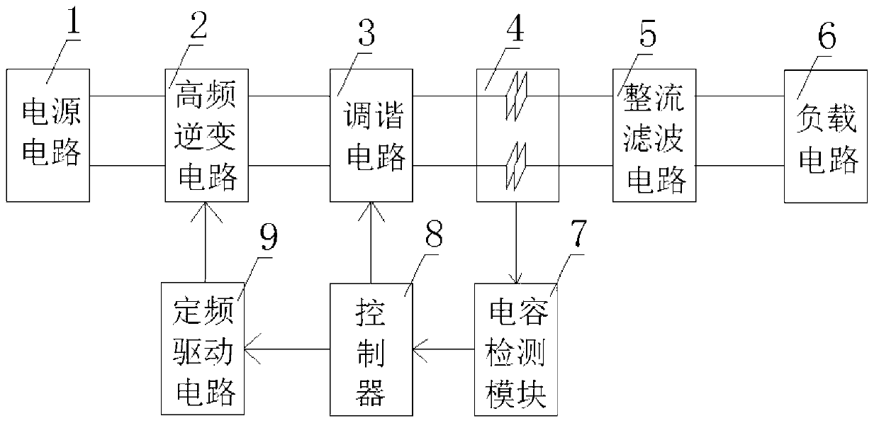
[0031] Such as figure 1As shown, a wireless power transmission system based on electric field coupling includes a power supply circuit 1, a high-frequency inverter circuit 2, a tuning circuit 3, an electric field coupling plate 4, a rectifier filter circuit 5, a load circuit 6, and a coupling capacitance detection module 7 , the controller 8 and the fixed-frequency drive circuit 9, the direct current provided by the power supply circuit 1 is converted by the high-frequency inverter circuit 2 to obtain high-frequency alternating current, the high-frequency alternating current is tuned by the tuning circuit 3, and finally loaded onto the electric field coupling plate 4, The electric field is coupled with the plate 4 to generate an alternating electric field, and under the action of the alternating elec...


PUM


Abstract

The invention discloses an electric field coupling-based wireless power transmission system. The system comprises a power supply circuit, a high-frequency inverter circuit, a tuning circuit, an electric field coupling polar plate, a rectifier filter circuit and a load circuit and is characterized by also comprising a coupling capacitance detection module, a controller and a fixed frequency drive circuit; a capacitance compensation array is arranged in the tuning circuit; the controller detects parameters of the electric field coupling polar plate and controls compensation values of the capacitance compensation array through the coupling capacitance detection module, and outputs fixed frequency control signals; and the fixed frequency signals are transmitted to the fixed frequency drive circuit, and then the high-frequency inverter circuit is driven to work. The electric field coupling-based wireless power transmission system has the advantages that based on the electric field coupling, the transmission capacity and efficiency of the system are improved by adopting an E amplifier; and by arranging the coupling capacitance detection module, the electric field coupling polar plate of the system is detected in real time, and the capacitance compensation value can be effectively controlled, so that the system is kept in the soft switching state, and the power transmission stability and reliability of the system are improved.

Description

technical field [0001] The present invention relates to wireless power transmission technology, in particular, a wireless power transmission system based on electric field coupling. Background technique [0002] With the advancement of science and technology, people have higher and higher requirements for power quality, requiring it to be portable, safe, efficient, and environmentally friendly. become possible. The so-called Wireless Power Transmission Technique refers to the comprehensive utilization of modern power electronics energy conversion technology, circuit theory, microelectronics technology and modern control technology to realize the power from the power supply (grid or battery) through soft media (such as electric field, Magnetic fields, microwaves, lasers, etc.) are transmitted to electrical equipment in a non-electrical contact mode, or electrical equipment returns energy to the power supply through a soft medium. [0003] At present, the research of wireles...

Claims


Application Information

Patent Timeline
Patent Type & Authority Applications(China)
IPC IPC(8): H02J17/00H02M3/28H02J50/05
CPCY02B70/1491Y02B70/10
Inventor 苏玉刚唐春森王智慧戴欣孙跃
Owner 重庆华创智能科技研究院有限公司
Why Eureka
Try Eureka