
Simple clamping device for ultrasonic inspection of residual stress of steel rail
A technology of residual stress and ultrasonic testing, applied in the direction of measuring devices, measuring forces, instruments, etc., can solve the problems that the overall measurement of rail head and rail waist, mobile measurement and in-service measurement cannot be realized
- Summary
- Abstract
- Description
- Claims
- Application Information
AI Technical Summary
Problems solved by technology
Method used
Image

Examples
Embodiment Construction
[0015] The specific embodiment of the present invention is described in detail below:
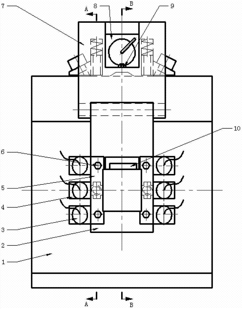
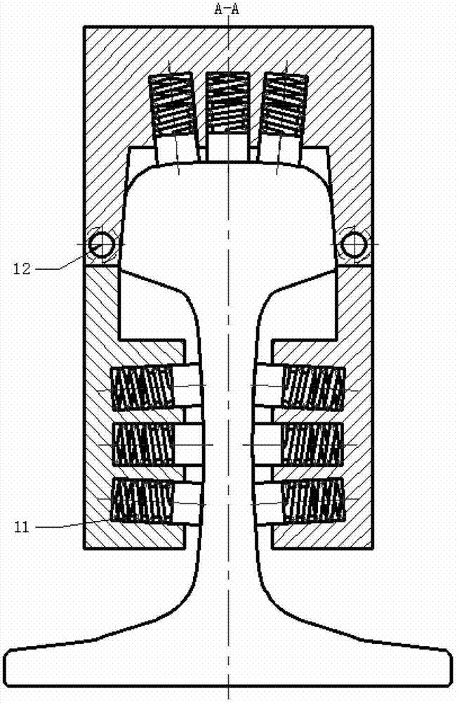
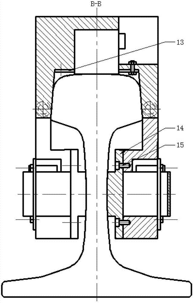
[0016] figure 1 Among them, the rail head magnetic seat 8 is embedded in the guide support frame 7, and the rail head magnetic seat is fixed on the guide support frame 7 by using the pressure plate 13 and the pressure plate bolt 9. Combine the probe 3 with the plexiglass wedge 4 , place the spring 11 in the groove in the plexiglass wedge 4 and install it in the corresponding installation hole of the guide support frame 7 . Place the assembled guide support frame 7 on the steel rail 1 to be tested stably. The magnetically conductive fixing plate 14 is fixedly connected with the mounting plate 2 by using the fixing plate screws 15, the rail waist magnetic base 10 is embedded in the mounting plate 2 and the bottom surface is closely attached to the magnetically conductive fixing plate 14, and the magnetic base cover plate 5 Fix and connect the rail waist magnetic base 10 and the strapping pl...
PUM
 Abstract
Description
Claims
Application Information