Gear grinding method

A gear and grinding technology, which is applied to gear tooth manufacturing devices, grinding/polishing equipment, belts/chains/gears, etc., can solve the problems of waste of grinding action and loss of processing time, and achieve the prevention of grinding burns and processing Effect of Accuracy Improvement

Active Publication Date: 2014-11-26
MITSUBISHI HEAVY IND MACHINE TOOL CO LTD
View PDF7 Cites 0 Cited by
  • Summary
  • Abstract
  • Description
  • Claims
  • Application Information

AI Technical Summary

Problems solved by technology

As a result, the grinding operation by the amount of the grinding wheel is wasted, which may result in a loss of processing time.

Method used


Image

  • Gear grinding method
  • Gear grinding method
  • Gear grinding method

Examples


Embodiment Construction

[0031] Hereinafter, the gear grinding method of the present invention will be described in detail using the drawings.

[0032] 【Example】

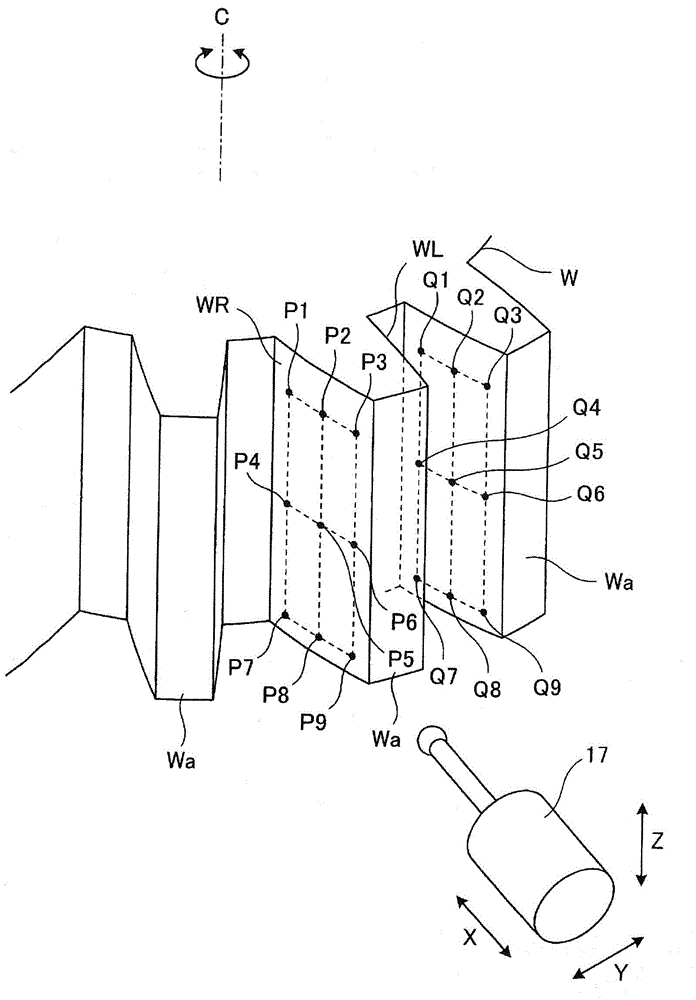
[0033] Such as figure 1 As shown, the rotary table 21 is mounted rotatably about a vertical workpiece axis of rotation C on the gear grinding wheel 1 . Further, a detachable workpiece (gear to be measured, gear to be processed) W is mounted on the upper surface of the rotary table 21 . Therefore, the workpiece W can be rotated around the workpiece rotation axis C by driving the rotary table 21 .

[0034] In addition, the grinding wheel head 11 is provided on the gear grinding table 1 so as to face the rotary table 21 . Further, the grinding wheel head 11 is supported so as to be movable along the X-axis, Y-axis, and Z-axis directions which represent the orthogonal three-axis directions of front-rear, left-right, and up-down, and to be rotatable about a horizontal grinding wheel turning axis A.

[0035] On the front surface of the grindi...


PUM


Abstract

Provided is a gear grinding method wherein an initial cutting position by a grindstone is appropriately set, resulting in an improvement being able to be made in machining accuracy. For this purpose, the gear grinding method is such that rotation of a workpiece (W) about a workpiece rotation axis (C), cutting by a grindstone (15) in the X-axis direction, and feeding of the grindstone (15) in the Z-axis direction are controlled, resulting in the workpiece (W) being ground by the grindstone (15). In this method, measurement points (P1 - P9) are set in a grid-like pattern on a left tooth surface (WL) and a right tooth surface (WR) of a predetermined tooth (Wa) of the workpiece (W); rotation phases about the workpiece rotation axis (C) at the measurement points (P1 - P9) are detected; tooth thickness deviation amounts (e) between a reference involute tooth surface and the measurement points (P1 - P9) on the left and right tooth surfaces, as well as tooth thickness deviation amounts (e) between the involute tooth surface and corresponding points (Q1 - Q9) on all teeth other than the tooth (Wa), are obtained on the basis of the detected rotation phases; and an initial cutting position (X1) for the grindstone (15) is set on the basis of the largest of the deviation amounts (e) .

Description

technical field [0001] The present invention relates to a gear grinding method for appropriately setting an initial cutting position in a cutting direction of a grinding wheel when grinding a gear to be processed. Background technique [0002] Conventionally, as a method of grinding and finishing a gear, there has been provided a profile grinding method in which a tooth surface of a gear is profile-finished using a grinding wheel. In this form grinding, first, the grinding wheel that has been meshed with the gear is moved in the radial direction of the gear, and positioned at the processing start position set at the initial cutting position, and then the grinding wheel is Grinding one tooth or one groove of the gear by moving along the rotation axis direction of the gear (at the initial cutting position). Then, when the grinding of all teeth or all grooves for the first time (first cycle) is completed, the grinding wheel is moved from the initial cutting position to the rad...

Claims


Application Information

Patent Timeline
Patent Type & Authority Patents(China)
IPC IPC(8): B23F23/00B23F5/02
CPCB23F23/00B24B19/00B23F19/002B23F5/02B23F23/006B23F23/1218
Inventor 柳濑吉言
Owner MITSUBISHI HEAVY IND MACHINE TOOL CO LTD
Why Eureka
Try Eureka