Mop barrel and novel mop matched with same

A new type of mop and mop bucket technology, applied in the field of mop buckets and mops matched with them, can solve problems such as failure to achieve normal work, difficulty in ensuring concentricity, and reduced friction, and achieve fewer parts, good concentricity, and friction loss. small effect

Inactive Publication Date: 2014-12-10
CIXI BOSHENG PLASTIC PROD
View PDF6 Cites 1 Cited by
  • Summary
  • Abstract
  • Description
  • Claims
  • Application Information

AI Technical Summary

Problems solved by technology

The disadvantages of the existing mops and mop buckets are that it takes a lot of effort to press down and turn the mop rod.
The lower rotating body 4 is connected with the upper rotating body through the screw 7 after passing through the through opening, and the lower end of the lower rotating body 4 has a ring of positioning retaining rings to prevent the lower rotating body from falling off. It also has the disadvantage that the left friction of the plastic part is fixed The block 5 and the right friction fixed block 6 are in frictional contact with the upper end surface of the upper rotating body 3 of the plastic part, and the wear is relatively large. After a long working time, the friction between the two gradually decreases, and even the normal work cannot be realized; the upper rotating body 3 It is separated from the lower rotating body 4 and connected by screws 7, so the concentricity of the two is difficult to guarantee

Method used


Image

  • Mop barrel and novel mop matched with same
  • Mop barrel and novel mop matched with same
  • Mop barrel and novel mop matched with same

Examples


Embodiment Construction

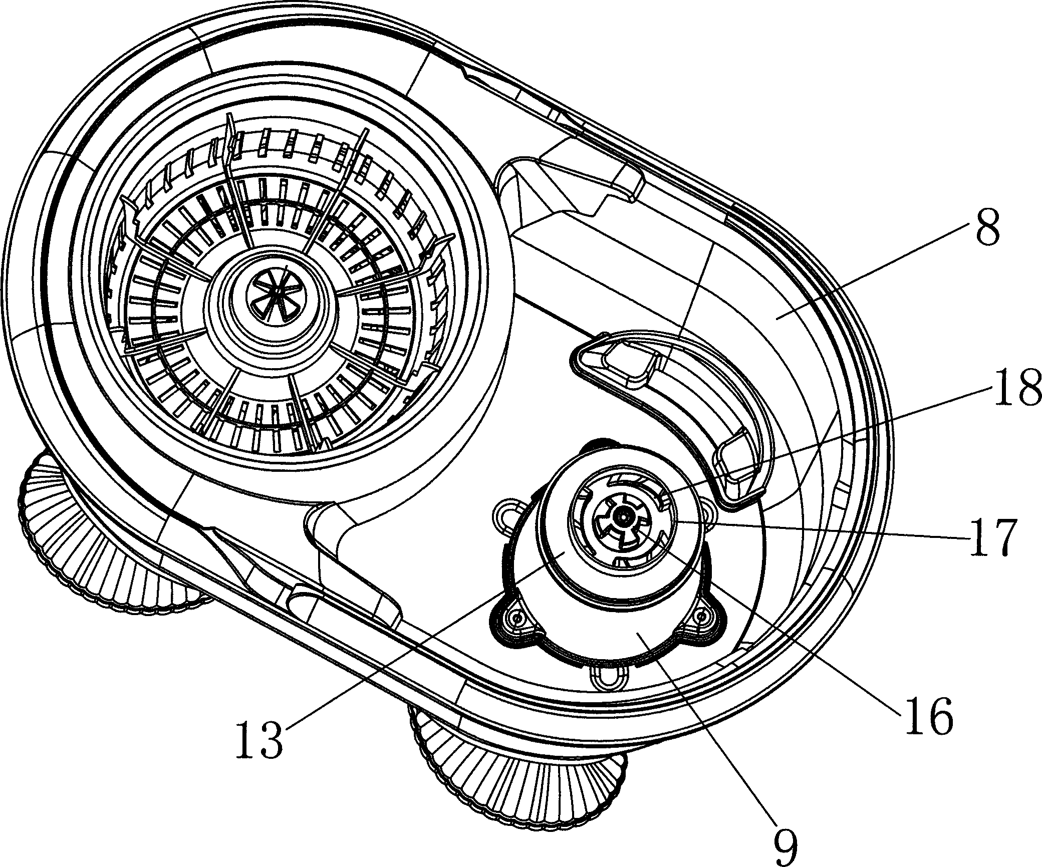
[0042] The present invention will be further described in detail below with reference to the drawings and specific embodiments.

[0043] Reference image 3 , Figure 4 , A mop bucket, including a bucket body 8, a deceleration device, the deceleration device includes a base 9 arranged on the bottom surface of the bucket body 8, the upper end of the base 9 is fixed with a chassis 10, the chassis 10 has A planetary gear accommodating cavity, the inner wall of the planetary gear accommodating cavity is provided with a ring gear. In this embodiment, the specific fixing method of the base 9 and the chassis 10 is as follows: the bottom surface of the chassis 10 has a fixed rod 11 extending downward, and the fixed rod 11 is provided with an axial positioning rib; the base 9 The upper end surface has a concave positioning groove 12, the side arm of the positioning groove 12 has a positioning groove that is adapted to the positioning rib, and the fixing rod 11 is inserted into the position...


PUM


Abstract

The invention provides a mop barrel, comprising a barrel body and further comprising a speed reducing device. The speed reducing device comprises a base; a chassis is fixedly arranged at the upper end of the base; a planet gear containing cavity is arranged on the chassis; a circle of a gear ring is arranged on the inner wall of the planet gear containing cavity; a rotating plate is covered on the chassis; a planet gear is arranged on the back face of the rotating plate; the planet gear is engaged with the gear ring; the mop barrel further comprises a sun wheel; the sun wheel is engaged with the planet gear; a driving head is further arranged at the upper end of the sun wheel; and a driven concave-convex part is further arranged on the upper end face of the rotating plate. The invention further provides the novel mop matched with the mop barrel; a friction fixing block on the mop is linked with a stainless steel cover sheet through friction force, and is integrated with a rotating body, so that the concentricity is good, and the more smooth rotation is realized. When a mop rod is vertically arranged, a left friction fixing block and a right friction fixing block are abutted against with a stainless steel cover sheet; and when the mop rod is reversely arranged, the left friction fixing block and the right friction fixing block are in friction with the stainless steel cover sheet. The left friction fixing block and the right friction fixing block are in friction with the stainless steel cover sheet so that the friction consumption is small and the service life is longer.

Description

(1) Technical field [0001] The invention relates to a mop bucket and a mop matched with it. (2) Background technology [0002] The hand-pressed rotary mop is more and more popular with home users. When using the hand-pressed rotary mop, press down on the mop, the mop rod will automatically rotate, thereby driving the mop plate at the bottom of the mop rod to rotate, which is convenient for washing the mop and mop And dehydration, washing and dehydration are carried out in the mop bucket. The existing mop and mop bucket still has the disadvantage that it takes more effort when the mop rod is pushed down to rotate. Therefore, a mop bucket with a deceleration device appears, which saves effort when pressing the mop rod. For example, the Chinese invention patent No. 201120157568.6 discloses such a mop bucket, but its deceleration device is very complicated, with many parts and transmission mechanism. It is complicated and therefore prone to failure. [0003] The structure of the exi...

Claims


Application Information

Patent Timeline
Patent Type & Authority Patents(China)
IPC IPC(8): A47L13/20A47L13/254A47L13/58
Inventor 黄智勇
Owner CIXI BOSHENG PLASTIC PROD
Why Eureka
Try Eureka