Single valve height pneumatic control system

A pneumatic control system and single valve technology, applied in the direction of engine components, machines/engines, non-mechanical actuated valves, etc., can solve problems such as liquid leakage, high sealing requirements, and delayed response speed of valve lift changes , to achieve the effect of fast response, simple structure and reasonable design

Inactive Publication Date: 2014-10-15
SHANGHAI JIAO TONG UNIV
View PDF1 Cites 0 Cited by
  • Summary
  • Abstract
  • Description
  • Claims
  • Application Information

AI Technical Summary

Problems solved by technology

However, its design is to use a hydraulic mechanism, which requires high sealing performance. If the sealing is not tight, it will easily cause liquid leakage; and because the liquid has a certain compressibility, the response speed of the valve lift change has a certain delay.

Method used


Image

  • Single valve height pneumatic control system
  • Single valve height pneumatic control system

Examples


Embodiment

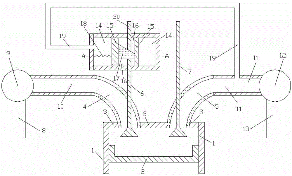
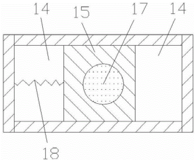
[0013] Such as figure 1 and figure 2 Shown, the present invention comprises: comprise cylinder 1, piston 2, cylinder head 3, intake passage 4, exhaust passage 5, intake valve lower section 6, exhaust valve 7, compressor intake pipe 8, compressor 9, engine Intake pipe 10, engine exhaust pipe 11, turbine 12, turbine outlet pipe 13, volume cavity 14, moving body 15, through pipe 16, moving block 17, spring 18, connecting pipe 19 and intake valve upper section 20, piston 2 installation In the space enclosed by the cylinder 1 and in sealing contact with the inner wall of the cylinder 1, the air outlet of the air intake passage 4 and the air inlet of the exhaust passage 5 are all connected with the cylinder head 3, and the air inlet and outlet of the compressor 9 are respectively Be connected with the air outlet of compressor air intake pipe 8, the air inlet of engine air intake pipe 10, the air outlet of engine air inlet pipe 10 is connected with the air inlet of air intake passa...


PUM


Abstract

A single-valve height pneumatic control system in the technical field of mechanical design, including: intake port, exhaust port, intake valve lower section, exhaust valve, intake valve upper section, volume cavity, moving body, through pipe, moving block, The connecting pipe and the spring, the moving body is installed in the volume chamber and is in sealing contact with the inner wall of the volume chamber, the penetrating pipe runs through the upper and lower walls of the moving body, the moving block is installed in the penetrating pipe and is in sealing contact with the inner wall of the penetrating pipe, the moving block The lower end surface of the moving body is a plane, the upper end surface of the moving block is an inclined plane, the two ends of the connecting pipe are respectively connected with the intake pipe and the left wall of the volume cavity, and the left wall of the moving body is connected with the left wall of the volume cavity through a spring. When the pressure in the exhaust pipe of the engine is high, the moving body moves to the right, and the lift of the intake valve becomes larger; when the pressure in the exhaust pipe of the engine is low, the moving body moves to the left, and the lift of the intake valve becomes small. The invention has reasonable design and simple structure, and is suitable for a variable valve lift system of a supercharged engine.

Description

technical field [0001] The invention relates to an engine air intake system in the technical field of mechanical design, in particular to a single valve height pneumatic control system. Background technique [0002] The valve lift of the traditional gasoline engine is fixed and invariable, that is, there is only one cam profile of the camshaft, which makes it impossible for the lift to make the engine respond well in both high-speed and low-speed areas. The valve lift or cam profile design of a traditional gasoline engine is a balanced choice for the engine under all operating conditions. As a result, the engine can neither get the best high-speed efficiency nor the best low-speed torque, but it can get The most balanced performance under all working conditions. The adoption of variable valve lift enables the engine to obtain the required valve lift in both high-speed and low-speed areas, thereby improving the high-speed power and low-speed torque of the engine. [0003] A...

Claims


Application Information

Patent Timeline
Patent Type & Authority Patents(China)
IPC IPC(8): F01L9/02F01L13/00
Inventor 韦红雨
Owner SHANGHAI JIAO TONG UNIV
Why Eureka
Try Eureka