A bidirectionally rotatable ratchet unfolding flywheel for ball screw inertial capacity

A ball screw, two-way rotation technology, applied in flywheels, one-way clutches, belts/chains/gears, etc., can solve the problems of constant moment of inertia of flywheels, difficulty in bearing instantaneous large loads, etc., and achieve compact structure and low manufacturing cost , the effect of good engineering application value

Active Publication Date: 2022-06-21
NAT UNIV OF DEFENSE TECH
View PDF7 Cites 0 Cited by
  • Summary
  • Abstract
  • Description
  • Claims
  • Application Information

AI Technical Summary

Problems solved by technology

[0005] In view of the shortcomings of the flywheel used in the general inerter container in the above-mentioned prior art that the moment of inertia is not changeable and it is difficult to bear the instantaneous large load, it overcomes the impact caused by the inertial capacity of the general ball screw when changing the direction of rotation of the flywheel on the smoothness of the inertial capacity of the ball screw Problem, the present invention provides a bidirectionally rotatable ratchet expansion flywheel for ball screw inertial capacity, which ensures that the inertia coefficient remains unchanged when the ball screw inertial motion direction is switched; and each flywheel does not need to change the direction of rotation, thereby Reduce the impact of ball screw inertial capacity due to the change of flywheel rotation, and at the same time, without adding additional devices and using additional energy, the flywheel moment of inertia can be continuously variable and adaptive to different working conditions

Method used


Image

  • A bidirectionally rotatable ratchet unfolding flywheel for ball screw inertial capacity
  • A bidirectionally rotatable ratchet unfolding flywheel for ball screw inertial capacity
  • A bidirectionally rotatable ratchet unfolding flywheel for ball screw inertial capacity

Examples


Embodiment Construction

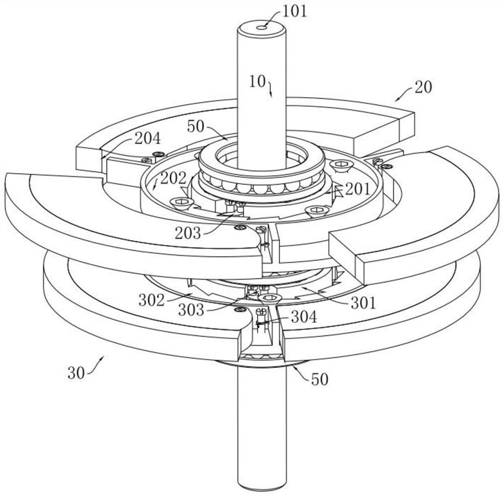
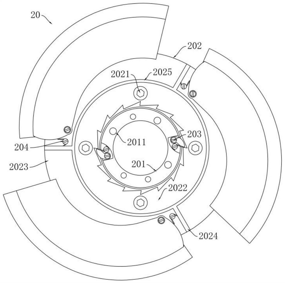
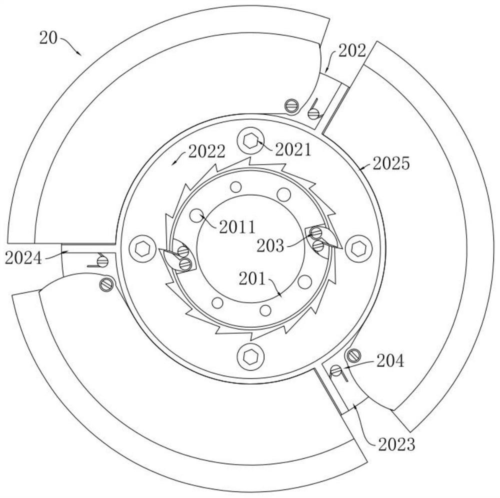
[0083] The technical solutions in the embodiments of the present invention will be clearly and completely described below with reference to the accompanying drawings in the embodiments of the present invention. Obviously, the described embodiments are only a part of the embodiments of the present invention, not all of the embodiments. Based on the embodiments of the present invention, all other embodiments obtained by those of ordinary skill in the art without creative efforts shall fall within the protection scope of the present invention.

[0084] It should be noted that all directional indications (such as up, down, left, right, front, back...) in the embodiments of the present invention are only used to explain the relationship between various components under a certain posture (as shown in the accompanying drawings). The relative positional relationship, the movement situation, etc., if the specific posture changes, the directional indication also changes accordingly.

[...


PUM


Abstract

The invention discloses a bidirectionally rotatable ratchet-deployable flywheel for ball screw inertial capacity, which includes a forward flywheel assembly and a reverse flywheel assembly; the forward flywheel assembly includes a forward dial, a forward flywheel disc and a forward expansion Mechanism, the forward dial is fixedly set on the screw nut assembly, the forward flywheel sleeve and the forward dial form a ratchet structure, and the forward expansion mechanism is set on the forward flywheel to change the rotation of the forward flywheel Radius; the reverse flywheel assembly includes a reverse dial, a reverse flywheel disc and a reverse expansion mechanism, the reverse flywheel and the reverse dial form a ratchet structure, and the reverse expansion mechanism is set on the reverse flywheel disc to change the reverse direction The radius of gyration of the flywheel. The impact caused by the change of the rotation direction of the flywheel when the inertial capacity of the ball screw switches the movement direction is realized without changing the rotation direction of the flywheel. At the same time, under the premise of not adding additional devices and using additional energy, the flywheel moment of inertia can be continuously variable and adaptive to different working conditions.

Description

technical field [0001] The invention relates to the technical field of vibration reduction of a flywheel type inertial container, in particular to a bidirectionally rotatable ratchet deployable flywheel used for ball screw inertial capacity, in particular to a vibration reduction system that can be used for a vibration reduction system including a ball screw inertial container Ratchet deployable flywheel with continuously variable moment of inertia and bidirectional rotation. Background technique [0002] In 2001, Smith of Cambridge University invented the "habit container". This new type of mechanical element can provide a very large amount of inertia with a small structural mass. The ideal inertial container element is defined as a single-channel mechanical element with two relatively independent and free-moving endpoints, and the forces at the two endpoints are equal in magnitude and opposite in direction, and are proportional to the relative acceleration. According to ...

Claims


Application Information

Patent Timeline
Patent Type & Authority Patents(China)
IPC IPC(8): F16F15/31F16F15/315F16F15/30F16D41/16F16H25/22
CPCF16F15/31F16F15/315F16F15/30F16D41/16F16H25/2204
Inventor 胡茑庆程哲李月昊陈凌沈建张伦罗鹏周洋
Owner NAT UNIV OF DEFENSE TECH
Why Eureka
Try Eureka