
Electrical switch

A technology for electric switches and rotor housings, which is applied in the field of electric switches and can solve problems such as small structural space and cost

Inactive Publication Date: 2016-08-17
SIEMENS AG
View PDF5 Cites 0 Cited by
  • Summary
  • Abstract
  • Description
  • Claims
  • Application Information

AI Technical Summary

Problems solved by technology

This structural solution is relatively expensive, because these structural solutions must be converted into the smallest structural space without impairing the normal function of the switch

Method used


Image

  • Electrical switch
  • Electrical switch
  • Electrical switch

Examples


Embodiment Construction

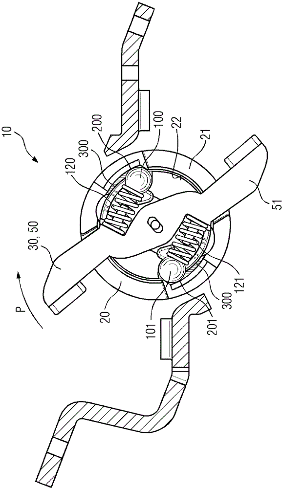
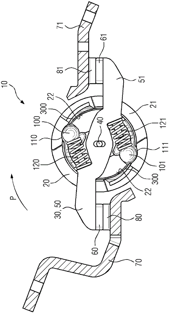
[0052] All figures are diagrammatic only and show the invention in its essential components. Wherein, the same reference numerals correspond to components with the same or comparable functions.

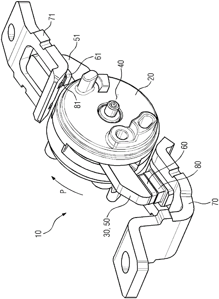
[0053] figure 1 Shown is an electrical switch 10 with a rotary contact system, which is similar to that in the so far unpublished German patent application "Electrical Switch" of the same applicant on January 25, 2011 (Internal Document No. 2010 24036) described in the electrical switch is the same.

[0054] The rotor housing 20 is rotatable in the direction of the arrow P about the axis of rotation 40 . Contact bridges or contact bridges 30 are arranged inside the rotor housing 20 , which can also rotate together with the rotor housing 20 or relative to the rotor housing 20 in the direction of the arrow P. Axis 40 revolves.

[0055] The contact bridge 30 is formed by a first contact arm 50 and a second contact arm 51 。 Each of the two contact arms 50 and 51 is provided at its en...


PUM


Abstract

The electrical switch (10) has function units whose surfaces are covered by a viscous guard material for protecting from contamination and damage. A swingable contact arm (50,51) is arranged in rotor housing (20), and interior of rotor housing is covered partially by guard material. An independent claim is included for a method for enhancing operation of electrical power switch.

Description

technical field [0001] The invention relates to an electrical switch, in particular a circuit breaker or power switch. Furthermore, the invention relates to a method for improving such a switch. Background technique [0002] Electrical circuit breakers or power switches usually have a rotary contact system with two contact elements, each connected to a current path and a rotatably mounted contact element that interacts with at least one of the fixed contacts. fixed point of contact. Movable contact elements, usually designed in the form of bridges, are used to interrupt and close electrical circuits. For example, the operating mechanism designed as a rocker structure is used for manual switching on or off. In the event of a short circuit, the contact bridges are to be opened rapidly electrodynamically independently of the actuating mechanism. [0003] When the contact bridges are opened, a switching arc occurs between the contacts which, at high temperatures, leads to ma...

Claims


Application Information

Patent Timeline
Patent Type & Authority Patents(China)
IPC IPC(8): H01H33/02H01H71/00
CPCH01H3/62H01H1/205H01H73/045H01H77/105
Inventor J.比纳W.费登B.汉尼奇T.普尼奥克
Owner SIEMENS AG
Learn More