Gyroscope sensor calibrating device and calibrating method

A calibration device and sensor technology, applied in the direction of instruments, measuring devices, etc., can solve problems such as batch calibration, and achieve the effects of improved efficiency, reasonable temperature control, and increased accuracy

Active Publication Date: 2013-04-03
张明铭
View PDF4 Cites 7 Cited by
  • Summary
  • Abstract
  • Description
  • Claims
  • Application Information

AI Technical Summary

Problems solved by technology

[0003] Aiming at the deficiencies in the prior art, the present invention provides a gyroscope sensor calibration device and a calibration method to solve the problem that the gyroscope sensor calibration device in the prior art cannot be calibrated in batches. Calibrate the circuit board equipped with MCU control chip, gyroscope sensor and acceleration sensor

Method used


Image

  • Gyroscope sensor calibrating device and calibrating method
  • Gyroscope sensor calibrating device and calibrating method
  • Gyroscope sensor calibrating device and calibrating method

Examples


Embodiment

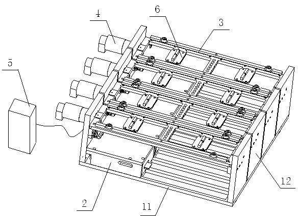
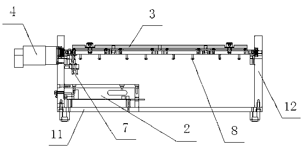
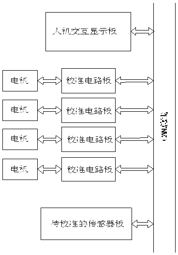
[0057] like figure 1 and figure 2 As shown, a gyroscope sensor calibration device includes a CAN bus, a fixed table, a calibration circuit board 2, a rotating frame 3 that can fix multiple sensor boards, a motor 4 that drives the rotating frame 3 to rotate, and a human-computer interaction display board 5. The fixed table is composed of a bottom plate 11 and side plates 12 symmetrically arranged on both sides of the bottom plate 11. The calibration circuit board 2 is placed on the bottom plate 11. on the side plates 12 on both sides of the bottom plate 11 . The rotating frame 3 is provided with a sensor slot device 6 for energizing and communicating with the sensor board, and the sensor slot device 6 is connected to the CAN bus. The motor 4 is installed on the side of the side plate 12 and is connected with the rotating shaft of the rotating frame 3 . The side plate 12 is also provided with a photoelectric limit switch 7 for controlling the operation of the motor 4 and det...


PUM


Abstract

The invention discloses a gyroscope sensor calibrating device which comprises a CAN (Controller Area Network) bus, a fixing table, a calibration circuit board, a rotating bracket capable of fixing a plurality of sensor plates, motors for driving the rotating bracket to rotate and a man-machine interaction display board, wherein the fixing table consists of a bottom plate and side plates which are symmetrically arranged on two sides of the bottom plate; the calibration circuit board is arranged on the bottom plate; two ends of a rotating shaft of the rotating bracket are respectively installed on the side plates on two sides of the bottom plate; sensor slot devices through which the sensor plates are supplied with power and communicate with other components are arranged on the rotating bracket; the sensor slot devices are connected with the CAN bus; the motors are installed on the side surfaces of the side plates and are connected with the rotating shaft of the rotating bracket; photoelectric limiting switches for controlling the motors to operate and detecting the position of the rotating bracket are further arranged on the side plates; and both the calibration circuit board and the man-machine interaction display plate are connected with the CAN bus. The invention also discloses a calibrating method of a gyroscope sensor.

Description

technical field [0001] The invention relates to a gyroscope sensor calibration device and a calibration method. Background technique [0002] All the gyroscope sensors in the prior art have the problem of temperature drift, which brings great inconvenience to some enterprises that require intelligent instruments and equipment with high dynamic performance. Although some higher-priced gyroscope sensors have less temperature drift compared with cheaper gyroscope sensors, they increase the economic burden of enterprises. In view of this, calibrating the gyroscope sensor has become a way for many companies to reduce costs. However, the device for calibrating the gyroscope sensor in the prior art has a relatively low calibration efficiency and cannot batch gyroscope sensors. The angular velocity and acceleration are calibrated, and most of the processes still require manual operation. SUMMARY OF THE INVENTION [0003] In view of the deficiencies in the prior art, the present...

Claims


Application Information

Patent Timeline
Patent Type & Authority Applications(China)
IPC IPC(8): G01C25/00
Inventor 郭盖华李星乐周伟
Owner 张明铭
Why Eureka
Try Eureka