
A clutch torque dynamic self-calibration platform and method

A clutch torque and clutch technology, applied in the direction of instrumentation, force/torque/power measuring instrument calibration/testing, measuring devices, etc., can solve the problems of insufficient applicability and insufficient detection dynamic performance

Active Publication Date: 2021-01-29
CHONGQING INST OF GREEN & INTELLIGENT TECH CHINESE ACADEMY OF SCI
View PDF12 Cites 0 Cited by
  • Summary
  • Abstract
  • Description
  • Claims
  • Application Information

AI Technical Summary

Problems solved by technology

[0005] In view of this, the purpose of the present invention is to provide a clutch torque dynamic self-calibration platform and method, which solves the problem of insufficient dynamic performance and insufficient applicability of the calibration method in the prior art. The present invention can monitor the torque of the main output shaft in real time Changes, combined with the operating status of the equipment, real-time protection of equipment safety, reducing failure losses

Method used


Image

  • A clutch torque dynamic self-calibration platform and method
  • A clutch torque dynamic self-calibration platform and method
  • A clutch torque dynamic self-calibration platform and method

Examples


Embodiment 1

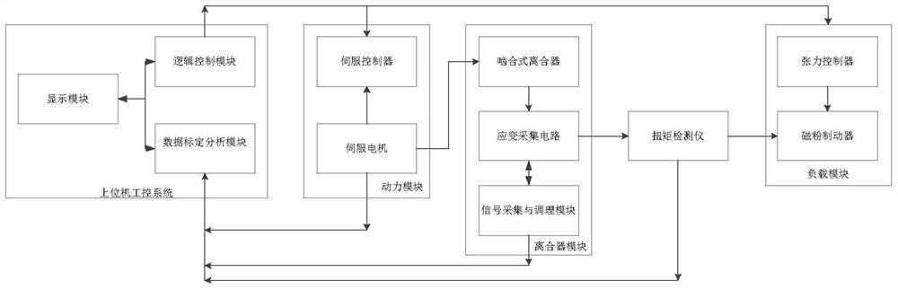
[0049] see figure 1 , is a functional frame diagram of an embodiment of a clutch torque dynamic self-calibration platform of the present invention. Specifically, the clutch torque dynamic self-calibration platform of this embodiment includes a power module, a clutch module, a torque detector and a power module connected in sequence. A load module, and an upper computer industrial control system connected with the power module, the clutch module, the torque detector and the load module.

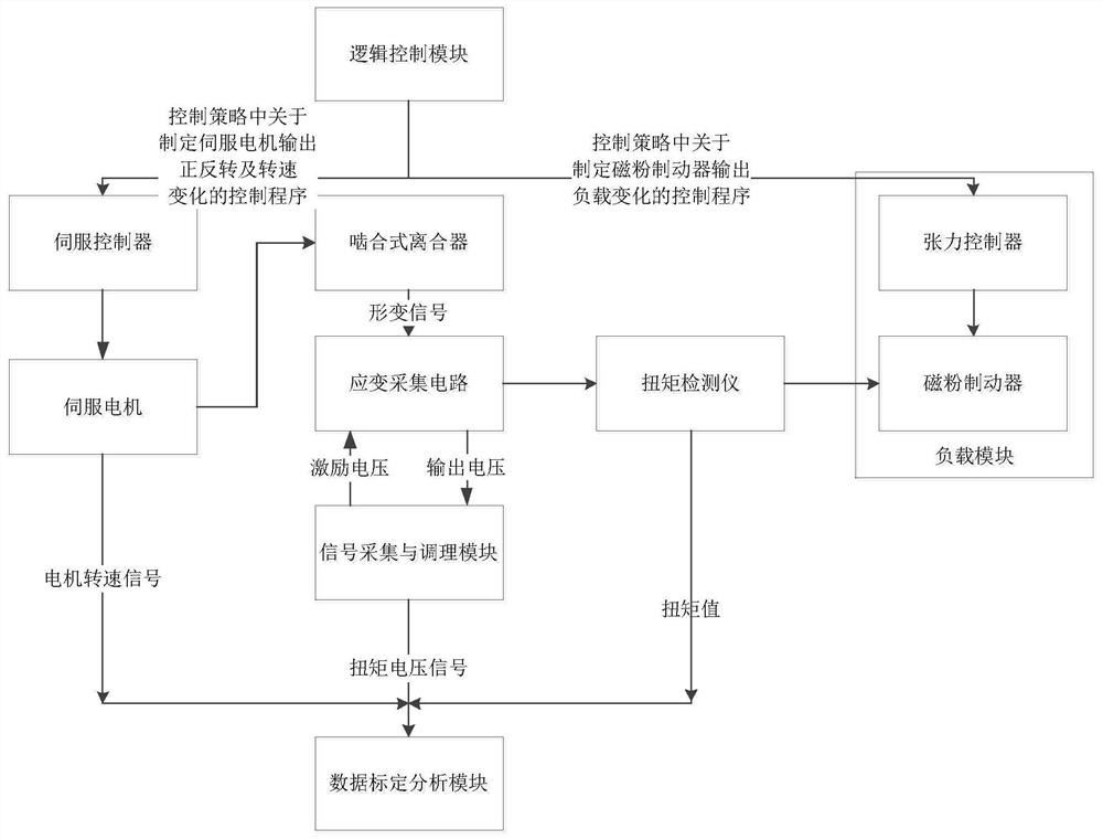
[0050] see figure 1 with figure 2 , in this embodiment, the upper computer industrial control system includes a connected data calibration analysis module and a logic control module, wherein the data calibration analysis module is connected with the power module, the clutch module and the torque detector respectively, and is used to obtain the clutch module (middle) in real time. The torque voltage signal (that is, the output voltage) of the strain acquisition circuit) and the torque value ...

Embodiment 2

[0073] Based on the clutch torque dynamic self-calibration platform in the first embodiment above, the present invention also provides a clutch torque dynamic self-calibration method, which will be described in detail below with reference to specific embodiments and accompanying drawings.

[0074] see Figure 5 , is a flowchart of an embodiment of a clutch torque dynamic self-calibration method of the present invention, specifically, the clutch torque dynamic self-calibration method described in this embodiment includes steps:

[0075] S1, formulate a control strategy in advance according to the disengagement torque range of the clutch, so as to adjust the output of the power module and the load module respectively according to the control strategy.

[0076] In this embodiment, the disengagement torque range of the clutch is theoretically estimated based on the inherent characteristics of the clutch in the above-mentioned clutch module and the basic theoretical formula of the ...


PUM


Abstract

The invention discloses a clutch torque dynamic self-calibration platform, which includes a power module, a clutch module, a torque detector and a load module connected in sequence, and a host connected to the power module, clutch module, torque detector and load module machine industrial control system, and the upper computer industrial control system includes a connected data calibration analysis module and a logic control module, wherein the data calibration analysis module is respectively connected with the power module, torque sensor, and torque detector; the logic control The modules are respectively connected with the power module and the load module. The invention adjusts the output power of the power module according to the control strategy formulated in advance based on the inherent torque disengagement characteristics of the clutch, and automatically collects, transmits, and calibrates the strain signal, that is, through the matching of the collected signal characteristics, the inspection of the range and the limit torque are realized. calibration. Correspondingly, the present invention also provides a clutch torque dynamic self-calibration method.

Description

technical field [0001] The invention relates to the field of torque monitoring, in particular to a clutch torque dynamic self-calibration platform and method. Background technique [0002] The clutch is a power transmission device, which is mainly installed between the power device and the actuator to combine or disconnect the power transmission. According to different control methods, the clutch has mechanical control, hydraulic control, air control, vacuum source control, electromagnetic and other manipulation methods. According to the different friction modes, the clutches are divided into jaw type, single friction plate and multi-plate friction plate. [0003] Clutches have been widely used in industries, automobiles and other fields as well as construction machinery. For example, the domestic method to protect key equipment from overload damage is to set the motor current protection and use the mechanical overload clutch (also known as clutch torque limiter). However...

Claims


Application Information

Patent Timeline
Patent Type & Authority Patents(China)
IPC IPC(8): G01L25/00
CPCG01L25/003
Inventor 朱海鹏井光辉徐泽宇石明全张鹏赵迎王晓东陈昭明邹劲松
Owner CHONGQING INST OF GREEN & INTELLIGENT TECH CHINESE ACADEMY OF SCI
Learn More