Auxiliary graphical method for rating pipeline stress for solving engineering practical problems

An auxiliary graphics and pipeline technology, applied in special data processing applications, instruments, electrical digital data processing, etc., can solve problems such as fast, accurate, effective difficulties, and inability to have a deep understanding of pipeline stress

Active Publication Date: 2013-04-03
CHINA NUCLEAR POWER ENG CO LTD
View PDF2 Cites 4 Cited by
  • Summary
  • Abstract
  • Description
  • Claims
  • Application Information

AI Technical Summary

Problems solved by technology

There is currently no applicable method to display the results of considering or not considering the stress concentration, that is, the influence of the coefficient i
Program users cannot have a deep understanding of the stress in the pipeline, so when solving the pipeline stress problem, it is difficult to quickly, accurately and effectively understand the problem

Method used


Image

  • Auxiliary graphical method for rating pipeline stress for solving engineering practical problems
  • Auxiliary graphical method for rating pipeline stress for solving engineering practical problems
  • Auxiliary graphical method for rating pipeline stress for solving engineering practical problems

Examples


Embodiment

[0046] The specific steps of the auxiliary graphic method for pipeline stress assessment for practical engineering problems are as follows:

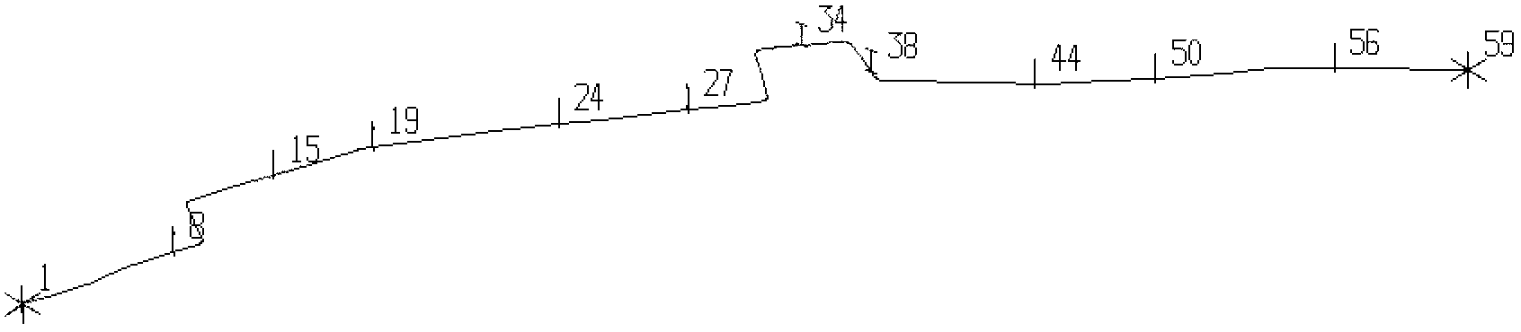
[0047] 1. First of all, when doing pipeline calculation, the unit should be divided very finely, for example, a unit of 1 mm (or even smaller), which can be realized by specifying the unit division coefficient. As mentioned above, when the length of the unit is required to be L according to the topic, when dividing the unit, use the length l to divide the unit, l=L*f, L is the length of the pipeline, and f can be set to be equal to 0.001 or even smaller.

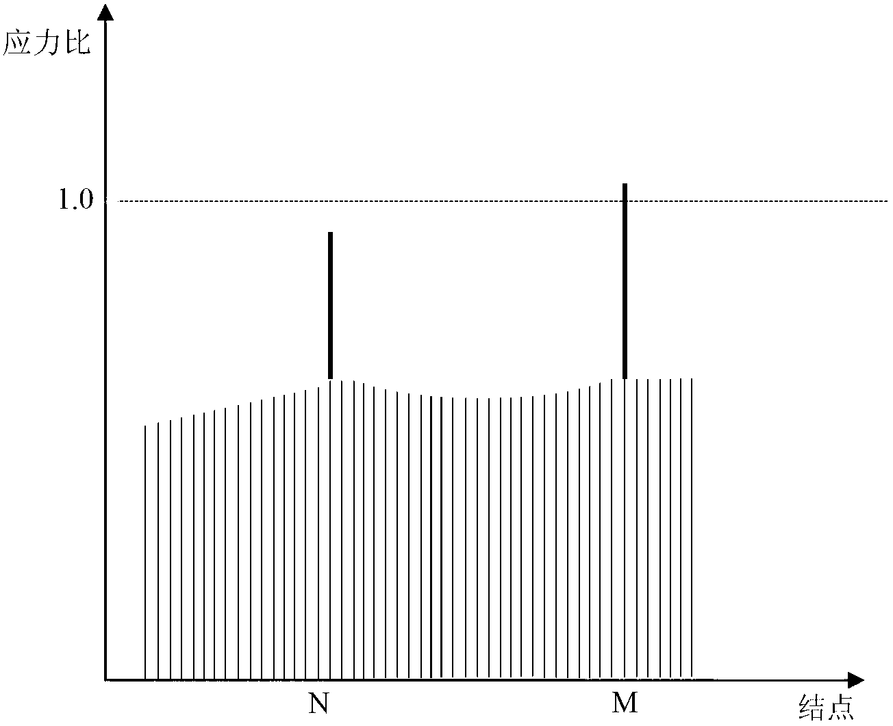
[0048] 2. Next, the finite element calculation is performed. When obtaining the calculated stress result, it is necessary to distinguish the stress value Sc without multiplying the stress concentration factor and the value Sr multiplied by the stress concentration factor. It is also possible to obtain the stress value Sc of each point without multiplying the stress concentration factor...


PUM


Abstract

The invention relates to a pipeline stress analyzing and computing technology, in particular to an auxiliary graphical method for rating pipeline stress used for engineering practical problems. The method comprises the following steps of: outputting a quantity which is irrelevant to stress concentration in computed stress and a quantity which is relevant to stress concentration respectively; and partitioning the quantity which is relevant to stress concentration into a quantity before the consideration of stress concentration and a quantity after the consideration of stress concentration, and displaying by using graphics. According to the method, a user can obtain more information from graphics, methods for solving problems can be found more quickly by using graphics, and solving of engineering problems is greatly facilitated.

Description

technical field [0001] The invention relates to pipeline stress analysis and calculation technology, in particular to an auxiliary graphics method for pipeline stress assessment for practical engineering problems. Background technique [0002] The current pipeline calculation is usually completed by the finite element method and the beam element calculation, and there are many stress output methods. However, the results of pipeline calculation are different from the general finite element stress results. The main difference is that the calculation rules of pipeline calculation determine that the calculated stress is not evenly distributed. See the calculation formula below: [0003] S SL = PD 0 4 t n + 0.75 i M A Z ...

Claims


Application Information

Patent Timeline
Patent Type & Authority Applications(China)
IPC IPC(8): G06F19/00
Inventor 刘树斌
Owner CHINA NUCLEAR POWER ENG CO LTD
Why Eureka
Try Eureka