Flat bottom trenching machine

A trough forming machine and flat bottom technology, which is applied in the direction of earth mover/excavator, construction, etc., can solve the problems of unallowable, high and uneven bottom of the trough

Inactive Publication Date: 2013-04-17
张永忠
View PDF4 Cites 4 Cited by
  • Summary
  • Abstract
  • Description
  • Claims
  • Application Information

AI Technical Summary

Problems solved by technology

[0002] At present, the multi-head slotting machine used in the construction of the underground diaphragm wall uses multiple drill bits to drill into the slot side by side. In order to ensure the maximum overlap width between the drill bits, the adjacent drill bits are staggered up and down

Method used


Image

  • Flat bottom trenching machine
  • Flat bottom trenching machine
  • Flat bottom trenching machine

Examples


Embodiment Construction

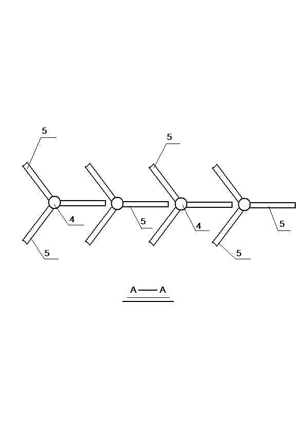
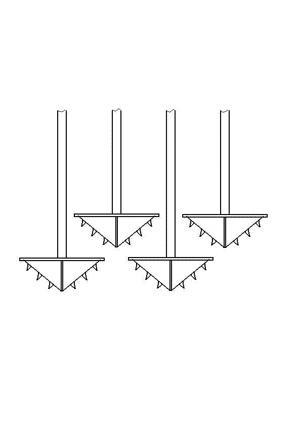
[0013] Accompanying drawing is a kind of concrete embodiment of the present invention, and this embodiment main drilling rod 1 lower end is provided with motor 2, and motor lower end is provided with gear box 3, and gear box lower end is provided with a plurality of drilling rods 4, and each drilling rod lower end is provided with There are three drill wings 5, and the three drill wings are in the same plane, and the angle between every two drill wings is 120°. The special feature is that every three drill wings under the multi-heel drill pipe are located on the same plane Inside, a drill wing of an adjacent drill rod is positioned between two drill wings of another drill rod.

[0014] When the present invention works, a plurality of drill rods rotate at a constant speed, wherein, the two drill rods on the left rotate forward, and the two drill rods on the right reverse. Rotate between two drill wings of another drill rod, and the drill wings do not fight with each other.


PUM


Abstract

Provided is a flat bottom trenching machine. The lower end of a main drill rod is provided with a motor, the lower end of the motor is provided with a gear box, the lower end of the gear box is provided with a plurality of drill rods, the lower end of each drill rod is provided with three drill wings, the three drill wings are in the same plane, and an included angle of every two drill wings is 120 degrees. The flat bottom trenching machine is characterized in that every three drill wings at the lower ends of the plurality of drill rods are located in the same plane, one drill wing of adjacent drill rods is located between two drill wings of another drill rod, and a formed tank bottom is a plane tank bottom.

Description

technical field [0001] The invention relates to a groove forming machine, in particular to a flat bottom groove forming machine for underground continuous wall groove formation. Background technique [0002] At present, the multi-head slotting machine used in the construction of the underground diaphragm wall uses multiple drill bits to drill into the slot side by side. In order to ensure the maximum overlap width between the drill bits, the adjacent drill bits are staggered up and down. Such as image 3 As shown, that is, the first and third drill bits are on the lower plane, and the second and fourth drill bits are on the upper plane. In this way, the groove bottom of the formed groove section has high depressions and unevenness, which is not allowed by the specification. Contents of the invention [0003] The present invention makes up for the above shortcomings and provides a flat bottom groove forming machine. [0004] The present invention is achieved through the fo...

Claims


Application Information

Patent Timeline
IPC IPC(8): E02F5/02
Inventor 张永忠
Owner 张永忠
Why Eureka
Try Eureka