Cutting insert, cutting tool, and method for producing cut product using said cutting insert and cutting tool

一种切削镶刀、切削刃的技术,应用在切削刀片、工具夹、制造工具等方向,能够解决切屑排出方向左右偏离、切屑排出性变劣等问题,达到排出方向稳定、提高排出性的效果

Active Publication Date: 2013-05-22
KYOCERA CORP
View PDF10 Cites 12 Cited by
  • Summary
  • Abstract
  • Description
  • Claims
  • Application Information

AI Technical Summary

Problems solved by technology

[0003] However, in such a cutting insert, for example, in the case of face grooving in which an annular groove is formed on the end surface of the workpiece, there is a difference in the cutting speed between the right end side and the left end side of the cutting edge, and there is a direction in which chips are discharged. Situations where it is easy to deviate to the left or right
In addition, due to the influence of the difference in cutting speed between the right end side and the left end side of the cutting edge, the curl diameters on the right end side and the left end side of the generated chips are different, so the chips are discharged helically. Therefore, as a result, there is Risk of poor chip discharge performance

Method used


Image

  • Cutting insert, cutting tool, and method for producing cut product using said cutting insert and cutting tool
  • Cutting insert, cutting tool, and method for producing cut product using said cutting insert and cutting tool
  • Cutting insert, cutting tool, and method for producing cut product using said cutting insert and cutting tool

Examples


no. 1 approach

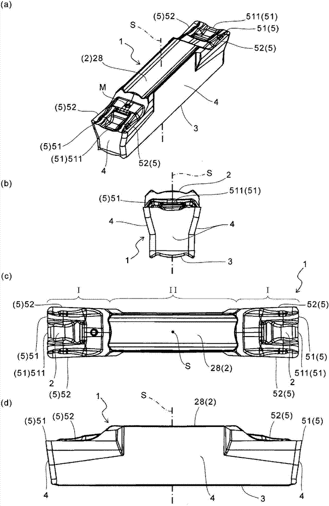
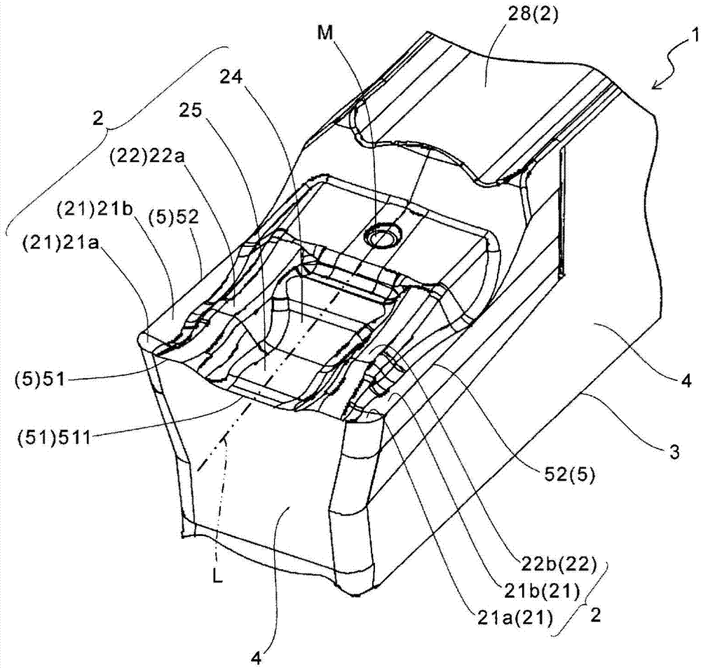
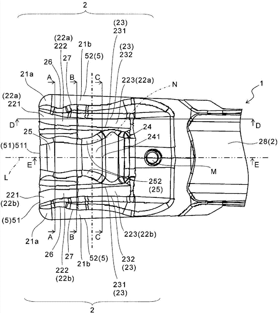
[0026] Below, refer to Figure 1 to Figure 7 A first embodiment of the cutting insert of the present invention will be described in detail.

[0027] Such as figure 1 As shown, the insert 1 of this embodiment has a prismatic shape and has: cutting parts I, I, which are located at both ends; and a clamping part II, which is located between the cutting parts I, I and has The toolholder 11 is the clamping surface 28 that is in contact with the toolholder 11, that is, the cutting part I is provided with a pair of two ends of the clamping part II. In this embodiment, if figure 1 As shown, in order to identify the cut portion I, a mark M is attached to one of the pair of cut portions I, I.

[0028] Examples of the material of the cutting insert 1 include cemented carbide, cermet, and the like. Examples of the composition of the cemented carbide include WC-Co obtained by adding cobalt (Co) powder to tungsten carbide (WC) and sintering, and WC-TiC-Co obtained by adding titanium car...

no. 2 approach

[0057] Second, refer to Figure 8 ~ Figure 11 The insert according to the second embodiment of the present invention will be described in detail. It should be noted that, in Figure 8 ~ Figure 11 , against the above Figure 1 to Figure 7 The same structural parts are denoted by the same symbols and descriptions thereof are omitted.

[0058] In plan view, it is preferred that the end 241' on the side away from the first cutting edge 51' in the central inclined portion 24', in other words, the end portion 241' on the higher side of the central inclined portion 24' and the second inclined The high end 223'u of the surface 223' is located on the same straight line, or is located behind the high end 223'u of the second inclined surface 223'.

[0059] In this embodiment, if Figure 9 As shown, the high end 241' of the central slope 24' and the high end 223'u of the second slope 223' are located on the same straight line. That is, if the straight line N' passing through the cent...


PUM


Abstract

The invention provides a cutting insert, a cutting tool, and a method for producing cut product using said cutting insert and cutting tool. The cutting insert according to the embodiments of the present application is provided with an upper surface, side surfaces, and a first cutting blade positioned at the intersection line of the upper surface and the side surfaces, wherein: the upper surface is provided with a pair of ridges positioned so as to face one another with the perpendicular bisector of the first cutting blade therebetween; the top portion of each ridge has at least two protrusions oriented in the direction along the aforementioned perpendicular bisector when viewed from above; and the aforementioned protrusions are provided with a first protruding section positioned the closest to the aforementioned perpendicular bisector, and a second protruding section positioned further away from the aforementioned perpendicular bisector than the first protruding section and at a higher position than the first protruding section. Also provided are a cutting tool provided with the aforementioned cutting insert and a method for producing a cut product by using said cutting tool.

Description

technical field [0001] The present invention relates to a cutting insert, a cutting tool, and a method of manufacturing a cut workpiece using the cutting tool. Background technique [0002] Regarding cutting inserts, especially cutting inserts used for parting or grooving, a structure that does not cause chips to contact the machined surface of the workpiece and damage the machining is being studied. Japanese Patent Application Laid-Open No. 2010-99815 discloses a cutting insert in which a cutting edge portion is formed at an end portion in the longitudinal direction of a shaft-shaped insert body and is oriented in the longitudinal direction and the width direction of the insert body. A cutting insert having a quadrangular rake face perpendicular to the thickness direction and forming band-shaped twisted surfaces extending in the longitudinal direction at both end portions in the width direction of the rake face. With this twisted surface, the chips can be sufficiently roll...

Claims


Application Information

Patent Timeline
Patent Type & Authority Applications(China)
IPC IPC(8): B23B27/22B23B27/04B23C5/20
CPCB23B29/043B23B27/045B23B1/00B23B27/1611B23B2220/126B23B2200/081Y10T82/10Y10T407/245Y10T407/2268Y10T407/24Y10T407/235Y10T407/25Y10T407/23
Inventor 井上善弘
Owner KYOCERA CORP
Why Eureka
Try Eureka