Cutting insert, cutting tool, and method for manufacturing cut product using cutting tool

一种切削镶刀、切削工具的技术,应用在铣削切削刀片、制造工具、刀夹的附件等方向,能够解决损伤切削镶刀、刀夹加工面、切屑堵塞、不能够舒畅地排出切屑等问题,达到减少切削阻力、刚性提高、优异切屑排出性的效果

Active Publication Date: 2012-08-22
KYOCERA CORP
View PDF9 Cites 2 Cited by
  • Summary
  • Abstract
  • Description
  • Claims
  • Application Information

AI Technical Summary

Problems solved by technology

[0003] However, in the above-mentioned conventional cutting inserts, there is a problem that finely cut chips cannot be smoothly discharged.
For example, the discharge direction of the chips generated by the split cutting edge is unstable, and the chips may clog the grooves and damage the cutting insert, tool holder, or machined surface.

Method used


Image

  • Cutting insert, cutting tool, and method for manufacturing cut product using cutting tool
  • Cutting insert, cutting tool, and method for manufacturing cut product using cutting tool
  • Cutting insert, cutting tool, and method for manufacturing cut product using cutting tool

Examples


no. 1 approach

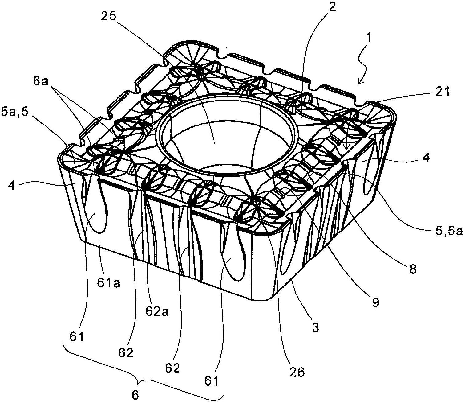
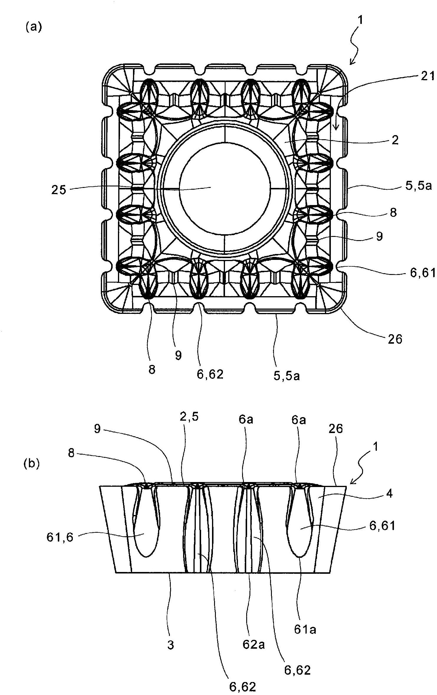
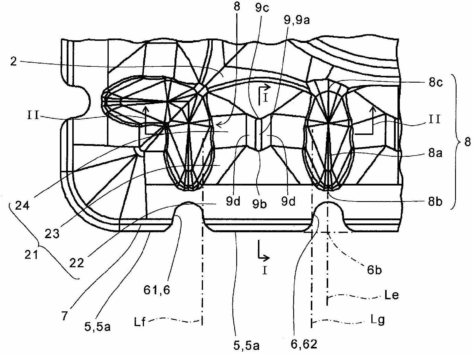
[0038] Below, refer to Figure 1 to Figure 5 The cutting insert (hereinafter referred to as "insert") according to the first embodiment of the present invention will be described in detail.

[0039] Such as figure 1As shown, the cutting insert 1 according to the present embodiment includes a main body having an upper surface 2, a lower surface 3, a side surface 4 located between the upper surface 2 and the lower surface 3, and a side surface 4 located between the upper surface 2 and the side surface 4. The cutting edge 5 of the intersection line.

[0040] The main body is composed of, for example, a member in which a film is coated on a sintered body such as cemented carbide, cermet, or ceramic. The film is for improving the wear resistance of the insert 1 . Examples of the film composition include titanium-based compounds such as titanium carbide, titanium nitride, and titanium carbonitride, or aluminum oxide. The film may be composed of at least one layer, and may be com...

no. 2 approach

[0079] Second, refer to Figure 6-10 The insert according to the second embodiment of the present invention will be described in detail. It should be noted that, in Figure 6-10 , for the above Figure 1~5 The same structural parts are marked with the same symbols and descriptions are omitted.

[0080] Such as Image 6 and Figure 7 As shown, the insert 31 according to the present embodiment includes a main body having an upper surface 32 , a lower surface 33 , and a side surface 34 . In the present embodiment, the main body has a quadrangular shape having four long sides and four corners with equal lengths.

[0081] In addition, in the insert 31, a cutting edge 35 is provided at the intersection of the upper surface 32 and the side surface 34, and as Figure 8 and Figure 9 As shown, the insert 31 is a so-called positive insert in which a positive relief angle θ3 is given to the side surface 34 . In the present embodiment, the relief angle θ3 is constant along the cut...

no. 3 approach

[0099] Second, refer to Figure 11 and Figure 12 An insert according to a third embodiment of the present invention will be described in detail. It should be noted that, in Figure 11 and Figure 12 , for the above Figure 1 to Figure 10 The same structural parts are marked with the same symbols and descriptions are omitted.

[0100] Such as Figure 11 As shown in (a), in the insert 31' according to this embodiment, the concave portion 36 is formed on the entire surface of the side surface 34, a plurality of divided cutting edges 35a are formed on the first side surface 34a, and a plurality of split cutting edges 35a are formed on the second side surface 34b. A plurality of divided cutting edges 35c are formed.

[0101] In this embodiment, three recesses 36a are formed on the first side surface 4a, and four recesses 36c are formed on the second side surface 34b. Therefore, the cutting edge 35 formed at the intersection of the first side surface 34a and the upper surfac...


PUM


Abstract

Provided is a cutting insert comprising: an upper surface; a lower surface; side surfaces which are located between the upper surface and the lower surface; one or more recesses which extend on the side surfaces in the thickness direction thereof and which each have one end located at the upper surface; and cutting edges which are located at the lines of intersection between the upper surface and the side surfaces and which are each divided into divided cutting edges by means of the recesses. The upper surface is provided with first protrusions which are located on the inner side of the recesses and also with second protrusions which are located on the inner side of the divided cutting edges. The second protrusions are each located, in a plan view, on the inner side of an end of each of the first protrusions, said end being that which is located on the cutting edge side. Also provided are a cutting tool provided with the cutting insert, and a method for manufacturing a cut product using the cutting tool.

Description

technical field [0001] The present invention relates to a cutting insert, a cutting tool equipped with the cutting insert, and a method of manufacturing a machined object using the cutting tool. Background technique [0002] Conventionally, as a cutting tool (rotary tool) such as a face mill or an end mill, a throw-away type in which cutting inserts are respectively attached to a plurality of insert pockets provided along the rotation direction of the outer peripheral surface of the front end of the holder is used. of cutting tools. As cutting inserts, cutting resistance is reduced by providing side surfaces with grooves for splitting cutting edges to form split cutting edges (see, for example, Japanese Patent Application Laid-Open No. 9-57519). When cutting is performed using this cutting insert, a large number of finely cut chips in the width direction are generated. [0003] However, in the above-mentioned conventional cutting inserts, there is a problem that finely cut...

Claims


Application Information

Patent Timeline
Patent Type & Authority Applications(China)
IPC IPC(8): B23C5/20B23B27/22B23C3/00B23C5/06
CPCB23C5/202B23C2200/128B23C2200/205B23C2200/323B23C2200/081B23C2200/082B23C5/06Y10T407/1924Y10T407/235Y10T409/303808Y10T407/23Y10T82/10B23C2200/326B23C2200/086
Inventor 石田琢也
Owner KYOCERA CORP
Why Eureka
Try Eureka