Rotating power transformer

A power transformer, rotary technology, applied in the direction of transformers, inductors, circuits, etc.

Active Publication Date: 2013-06-12
SCHLEIFRING & APPBAU
View PDF9 Cites 4 Cited by
  • Summary
  • Abstract
  • Description
  • Claims
  • Application Information

AI Technical Summary

Problems solved by technology

As a result, the internal diameter of such swivel joints can be greater

Method used


Image

  • Rotating power transformer
  • Rotating power transformer
  • Rotating power transformer

Examples


Embodiment Construction

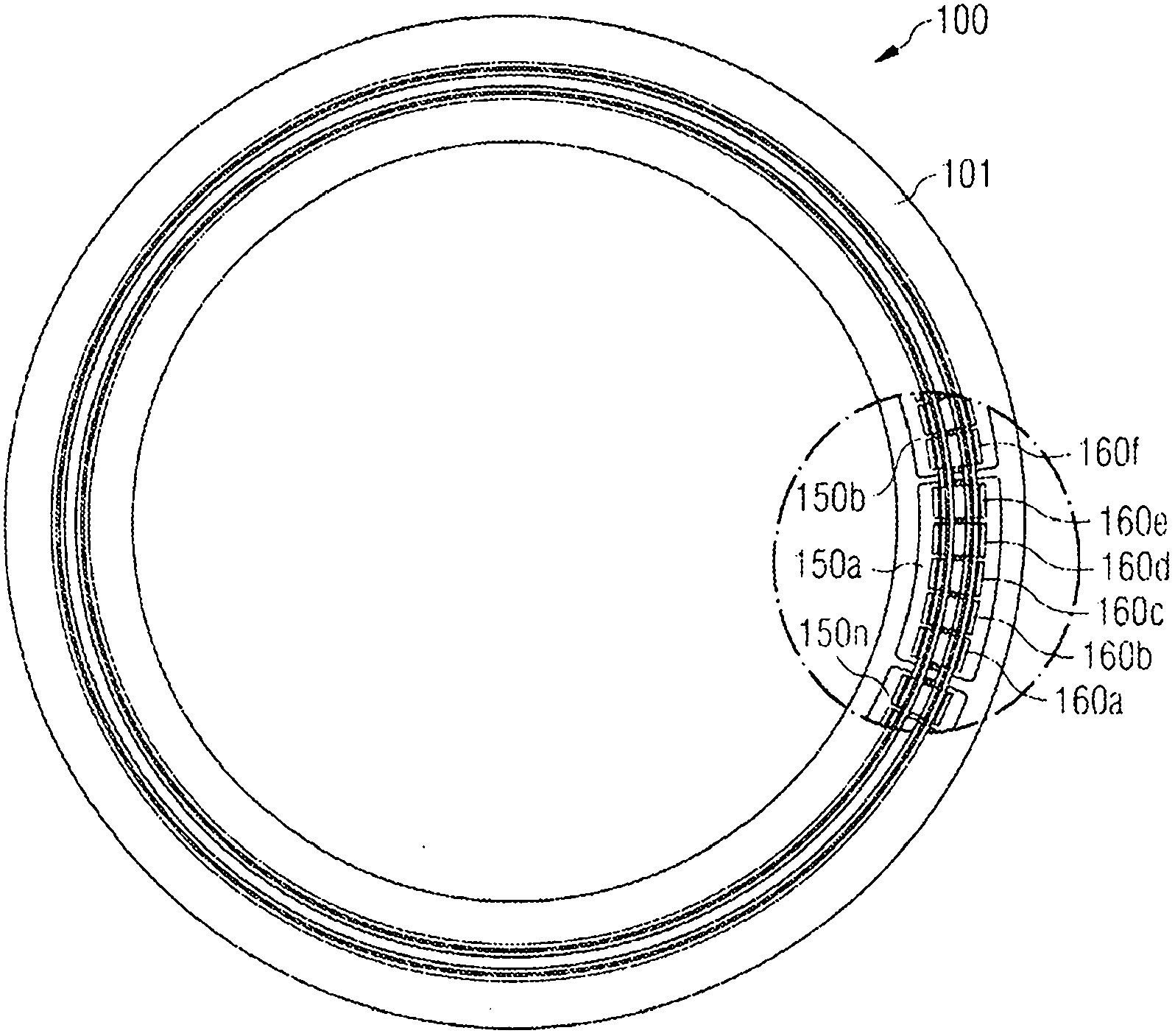
[0037] exist figure 1 In , a preferred embodiment of the present invention is shown. It shows one of two parts of the transformer. In general, a resolver has two similar components 100, one on the stationary side and the other on the rotating side. For simplicity, only one of these two components is described in detail. A number of transformer sections 150a...150n are provided. These transformer sections can be made of metal or plastic material. Due to the insulating properties of plastic materials, it is preferred to use fiber-reinforced plastic materials.

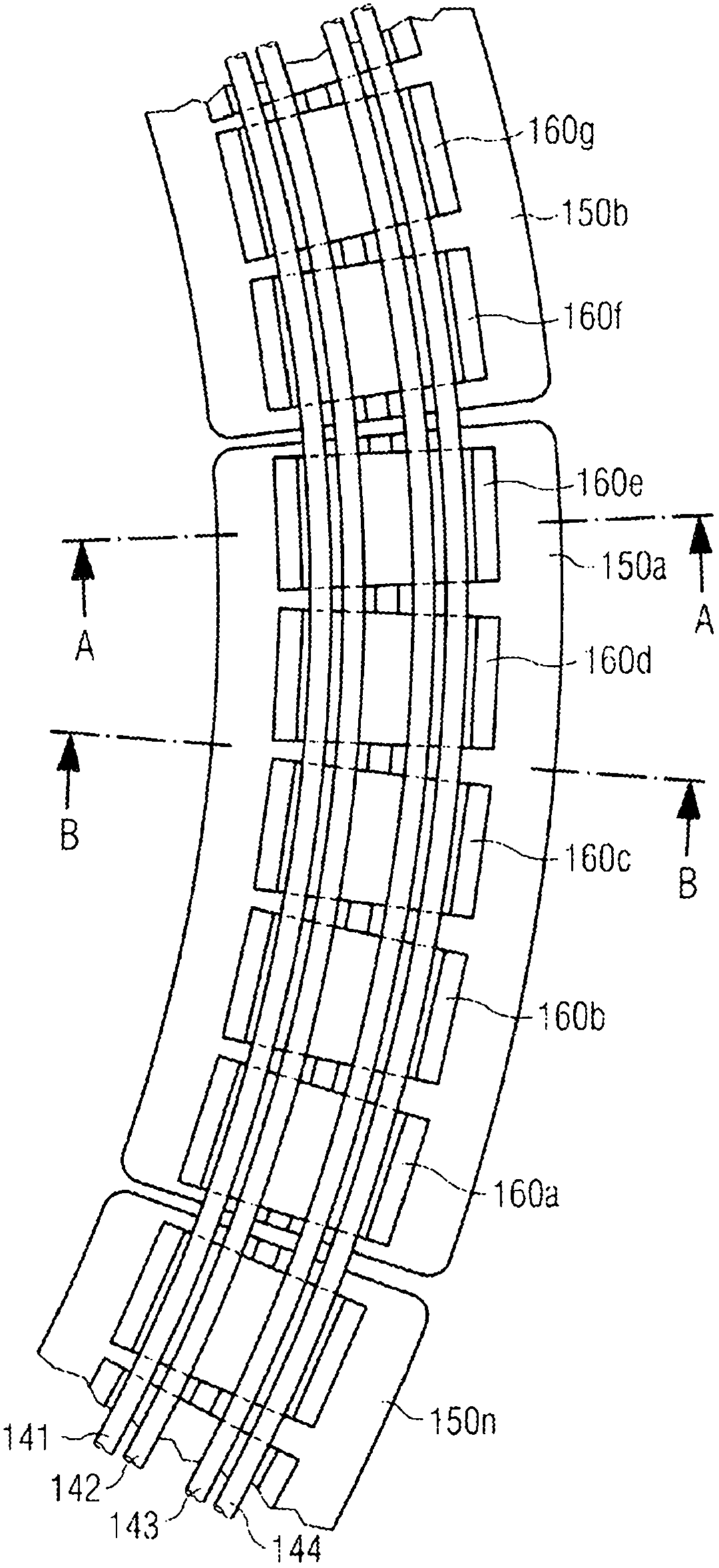
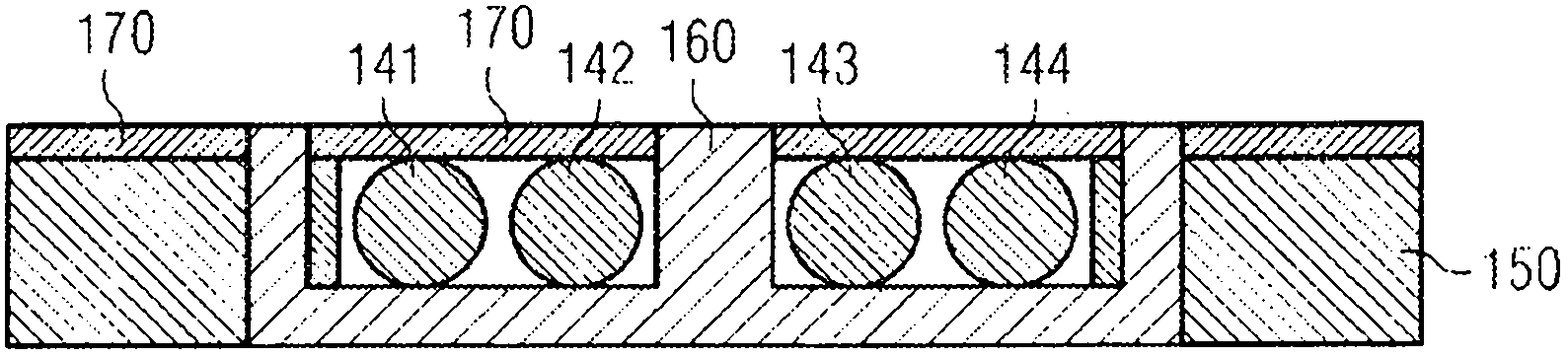
[0038] exist figure 2 , a segment of a rotary transformer is shown in detail. Transformer section 150a holds 5 soft magnetic cores 160a...160e. The windings are inside a soft magnetic core. The soft magnetic core may be a standard ferrite core with a rectangular cross-section, used in power transformers. The magnetic core can be E-shaped or U-shaped core. It is also possible to use two U-shaped cores combined i...


PUM


Abstract

A rotating power transformer has a stationary and a rotating part. At least one of these parts comprises a plurality of transformer segments which are preferably of plastic material. Rectangular shaped soft magnetic cores are held with within the transformer segments together with at least one winding located in the soft magnetic cores. This allows for a simple and efficient assembly of the rotating power transformer.

Description

technical field [0001] The present invention relates to contactless rotary joints, also called rotary power transformers, in particular for the transmission of high voltage electrical power. This non-contact rotary joint can be used in CT scanners. Background technique [0002] In US Pat. No. 7,197,113 B1 a contactless rotary joint comprising an inductive power coupler is disclosed. This rotary joint is capable of transferring hundreds of kilowatts of power from the stationary part to the rotating part. This swivel union has a thick-plated hot-dip galvanized iron core or a ferrite core for guiding the magnetic field. For example, in CT scanners, holes larger than one meter in diameter are required. As a result, such swivel joints can have an internal diameter greater than one meter, requiring large, strong mechanical support structures. [0003] European patent publication EP1481407B1 discloses a rotary transformer whose winding form consists of a plurality of shaped par...

Claims


Application Information

Patent Timeline
IPC IPC(8): H01F38/18
CPCH01F38/18
Inventor N·克鲁姆P·洛伊丝埃勒J·舍贝尔
Owner SCHLEIFRING & APPBAU
Why Eureka
Try Eureka