Electromagnetically driven high-speed cutting simulation experimental device

A high-speed cutting and experimental device technology, applied in the field of metal cutting, can solve the problems of limited energy, complex equipment, high experimental cost, etc., and achieve the effects of adjustable electromagnetic energy, fast cutting speed and short discharge time

Inactive Publication Date: 2013-06-19
SHANDONG UNIV
View PDF9 Cites 12 Cited by
  • Summary
  • Abstract
  • Description
  • Claims
  • Application Information

AI Technical Summary

Problems solved by technology

For example, the Chinese patent document (201110049605.6) discloses a high-speed cutting experimental device based on the Hopkinson compression bar loading technology. This cutting device uses a small-caliber light air gun to indirectly load the tool, and its energy is limited, so it is difficult to achieve extreme cutting. High cutting speed, and the sale and use of light air guns are prohibited by the state, so this device is not suitable for general scientific research; Chinese patent document (201210031362.8) discloses a high-speed cutting experimental device based on light air gun loading technology, the device It is also the indirect loading of the tool. Although it can achieve a high cutting speed, it also has the problems of complex equipment, high safety hazards, and high experimental costs; Chinese patent literature (201110308593.4) ​​discloses an explosive high-speed cutting device. The principle is to use the strong gas pressure generated by the explosion of gunpowder to drive the tool rod to drive the blade to hit the workpiece at high speed. This device has a simple structure and low cost, but it cannot control the cutting speed, and there are certain safety hazards when using gunpowder.

Method used


Image

  • Electromagnetically driven high-speed cutting simulation experimental device
  • Electromagnetically driven high-speed cutting simulation experimental device

Examples


Embodiment Construction

[0028] The present invention will be further described below in conjunction with the accompanying drawings and embodiments.

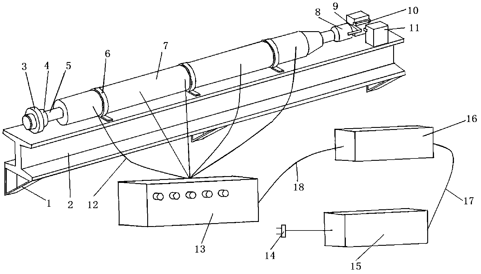
[0029] Such as figure 1 As shown, an electromagnetically driven high-speed cutting experimental device includes a power mechanism, a cutting mechanism and a fixing mechanism. The mechanism includes a tool clamping device 8 and a tool 9 installed thereon. The fixed mechanism includes a support frame 1, a support 2, a fixing hoop 6 and a workpiece clamping and positioning device 11. The electromagnetic driver 7 of the power mechanism It is fixed on the support 2 through the fixing hoop 6 , the support 2 is fixed on the wall through the supporting frame 1 , and the tool holding device 8 is installed on one end of the aluminum alloy rod 5 .

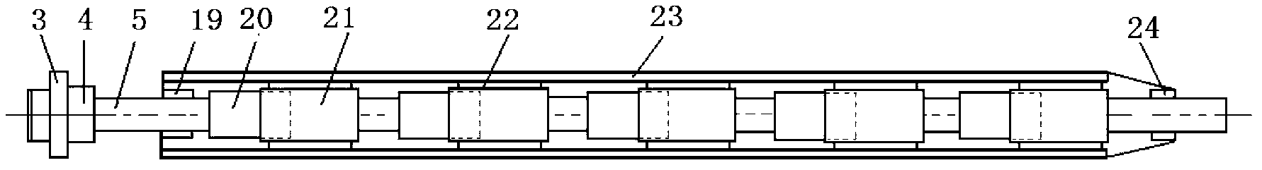
[0030] The electromagnetic driver 7 includes an aluminum alloy rod end stopper 3, a buffer pad 4, an aluminum alloy rod 5, the buffer pad 4 is set on the aluminum alloy rod 5, and the aluminum alloy rod end stopper 3 ...


PUM


Abstract

The invention discloses an electromagnetically driven high-speed cutting experimental device which comprises an actuating mechanism, a cutting mechanism and a fixing mechanism, wherein the actuating mechanism is used for producing electromagnetic thrust to drive the cutting mechanism to move at a high speed so as to enable a cutter to cut a workpiece fixed on the fixing mechanism, and the cutter can be rapidly stopped by a cushion and an aluminum alloy end check block on the actuating mechanism. The whole experimental device provided by the invention is constructed based on an electromagnetically driving technology, thus being economical, environment-friendly and good in stability, the experimental device can achieve a very high cutting speed, the cutting speed is adjustable, and a high-speed camera is additionally arranged and can be used for carrying out image processing and analysis on a high-speed cutting process. By matching with instruments such as a laser velocimeter and a dynamometer, the electromagnetically driven high-speed cutting experimental device can meet the requirements of high-speed cutting experiments of various materials.

Description

technical field [0001] The invention belongs to the field of metal cutting, in particular to an electromagnetic-driven high-speed cutting simulation experiment device. Background technique [0002] High-speed cutting is characterized by high efficiency, high precision and high surface quality. It has been widely used in the automotive industry, aerospace, mold manufacturing and instrumentation industries. It is an important part of contemporary advanced manufacturing technology. . [0003] The mechanism of high-speed cutting is the foundation of the development of high-speed cutting technology, and the experiment of high-speed cutting is an important means for the research of high-speed cutting technology. Through high-speed cutting experiments, not only can the deformation behavior and related laws of the processed material be revealed during high-speed cutting, but also the prediction results of high-speed cutting theory and finite element simulation results can be verifi...

Claims


Application Information

Patent Timeline
Patent Type & Authority Applications(China)
IPC IPC(8): G01N3/58
Inventor 刘战强张杨广万熠刘继刚
Owner SHANDONG UNIV
Why Eureka
Try Eureka