An in-situ transient temperature measuring device for high-speed cutting

A technology of high-speed cutting and temperature measuring device, applied in the field of metal cutting, can solve the problems of affecting accuracy, large error, and high, and achieve the effect of short duration and high speed

Active Publication Date: 2019-12-27
INST OF MECHANICS CHINESE ACAD OF SCI
View PDF8 Cites 0 Cited by
  • Summary
  • Abstract
  • Description
  • Claims
  • Application Information

AI Technical Summary

Problems solved by technology

Both natural thermocouple and artificial thermocouple are contact temperature measurement methods. The disadvantage of this type of temperature measurement method is that it will interfere with the cutting process, and the contact temperature measurement will have a long thermal equilibrium time, which will cause relatively long thermal stability when used in high-speed cutting. big error
Infrared radiation temperature measurement belongs to non-contact temperature measurement, but the time resolution of traditional infrared thermal imaging cameras is not high, and the distance from the measured surface will affect the accuracy
[0004] Recently, some foreign research institutions have used photoelectric detection methods to measure temperature. The photoelectric probe uses infrared radiation of different wavelengths to change the conductivity of the semiconductor to measure the temperature change. The photoelectric detection time resolution is high, and the non-contact will not affect the measured object. Influence, but the supporting infrared optical system has higher requirements, and the temperature calibration system has a very important impact on the accuracy of temperature measurement

Method used


Image

  • An in-situ transient temperature measuring device for high-speed cutting
  • An in-situ transient temperature measuring device for high-speed cutting

Examples


Embodiment 1

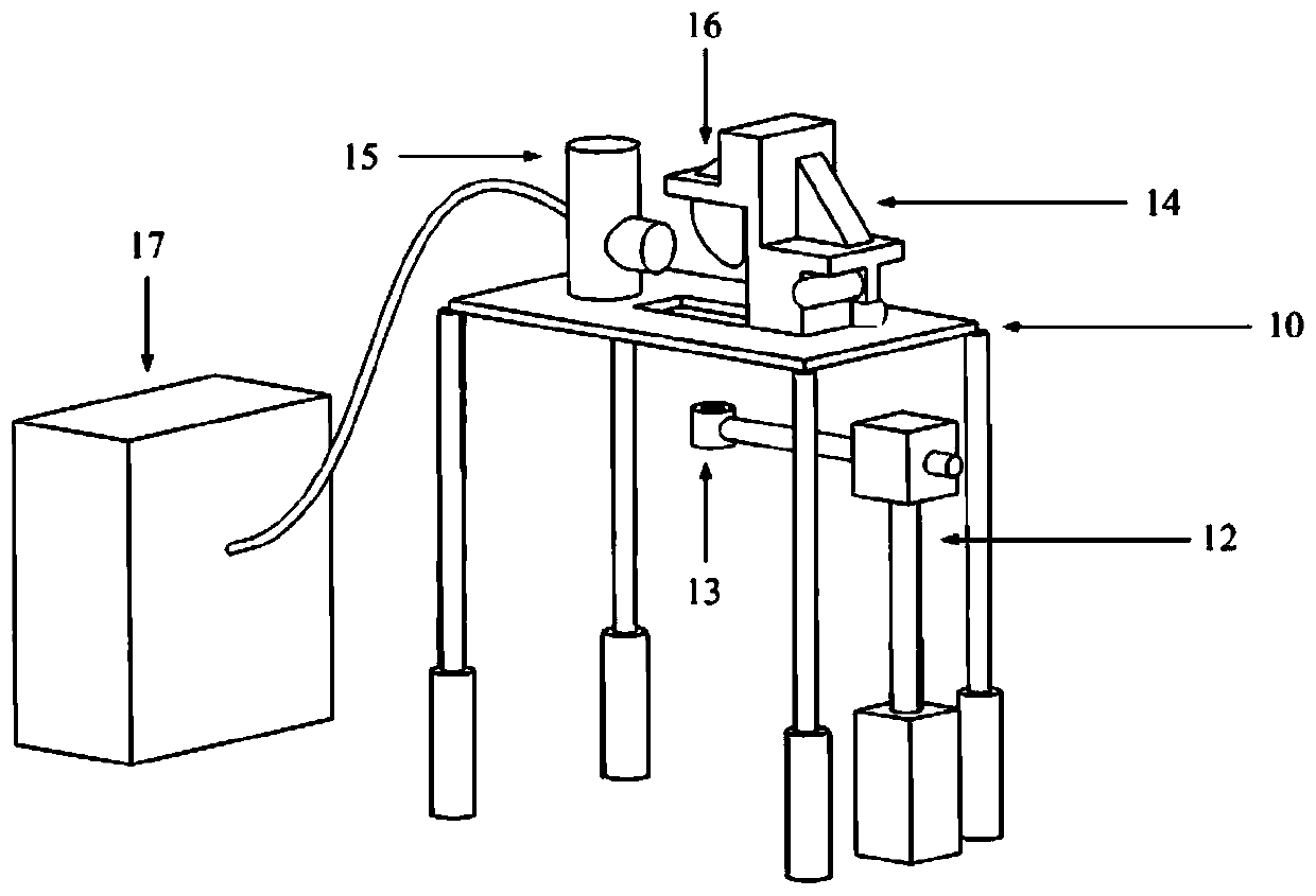
[0043] The whole device is installed on the support, and the specific implementation steps are as follows:

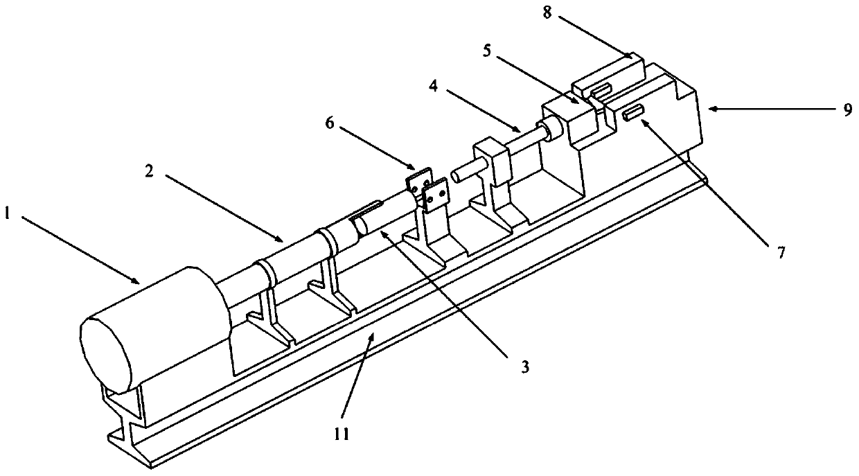
[0044] Such as figure 1 , 2 As shown, a workpiece 5 to be processed with a length of 40 mm, a width of 30 mm, and a thickness of 2 mm is installed on the front section of the incident rod, so that the workpiece 5 to be processed is protruded so as to adjust the relative position of the tool 7 and the workpiece 5 to be processed (depth of cut ).

[0045] The two tool clamping and high-precision positioning devices 8 are symmetrically installed on the high-precision lifting platform 9 along the axis of the acceleration barrel, and the distance between the two is guaranteed to be slightly larger than the tool width during the installation process. Install two tools with a thickness of 6mm, a rake angle of 0°, and a rear angle of 15° on the workpiece clamping and high-precision positioning device 8, and adjust the high-precision lifting table 9 to make the height of the w...

Embodiment 2

[0052] In the case of keeping the parameters in Example 2 unchanged, adjust the air pressure value of the light air gun 1 to make it 0.5MPa, and finally realize the cutting experiment with a cutting speed of 30m / s.


PUM


Abstract

The invention discloses an in-place transient state temperature measurement device for high-speed cutting, by means of the device, the high-speed cutting experiment requirement of most materials can be met, the whole cutting process can be high in speed, duration is short, impact energy is far larger than energy required for cutting, the process can be regarded as a steady-state process, and in-place real-time measurement can be conducted on the cutting process.The in-place transient state temperature measurement device comprises a cutting system, a Hopkinson rod power loading system, a positioning system, an infrared measurement system and a data acquisition system, wherein the cutting system is configured to conduct high-speed cutting on a workpiece to be machined; the Hopkinson rod power loading system is configured to push the cutting system to fly along a pre-selected orbit at a preset speed; the positioning system is configured to determine the position of a temperature measurement point; the infrared measurement system is configured to conduct temperature measurement; the data acquisition system is configured to acquire target data; the Hopkinson rod power loading system and the cutting system are sequentially arranged along an axis, the positioning system and the infrared measurement system are arranged to be perpendicular to axis, and the data acquisition system is connected with the infrared measurement system.

Description

technical field [0001] The invention belongs to the technical field of metal cutting, and in particular relates to an in-situ transient temperature measuring device for high-speed cutting. Background technique [0002] Manufacturing is a pillar industry of the national economy and a symbol of a country's comprehensive national strength. Advanced manufacturing is an important guarantee for promoting national economic development and enhancing national strength. As the most important advanced manufacturing technology, high-speed cutting can reduce cutting force by 30% and increase processing efficiency by more than 3 to 5 times, which has broad application prospects. One of the most important physical parameters of high-speed cutting is cutting temperature, which determines tool life, machining accuracy and machining integrity. However, there are still many issues to be studied about the cutting temperature of high-speed cutting. The most famous one is the Salomon hypothesis....

Claims


Application Information

Patent Timeline
Patent Type & Authority Patents(China)
IPC IPC(8): G01N3/58G01J5/00
CPCG01J5/00G01N3/58
Inventor 戴兰宏王祺叶贵根张虎生
Owner INST OF MECHANICS CHINESE ACAD OF SCI
Why Eureka
Try Eureka