Mechanical plate shearing machine

A shearing machine, a mechanical technology, applied in the direction of shearing equipment, shearing devices, metal processing equipment, etc., can solve the problems of increased production costs, short shearing strokes, etc., to improve production efficiency, improve forming quality, reduce The effect of preparation time

Inactive Publication Date: 2015-02-04
DALIAN UNIV OF TECH
View PDF8 Cites 0 Cited by
  • Summary
  • Abstract
  • Description
  • Claims
  • Application Information

AI Technical Summary

Problems solved by technology

Although the structure of the centering crank slider mechanism is simple and the manufacturing cost is low, the speed curve of the centering crank slider mechanism is close to a sinusoidal curve. When driving the inclined blade cutter to shear the plate, the speed changes greatly at different positions, and the quality of the incision is not uniform. It is often necessary to increase the process to process the incision, which greatly increases the production cost; in addition, the centering crank slider mechanism has no quick return characteristics, and the shearing plate can be used with a short stroke

Method used


Image

  • Mechanical plate shearing machine
  • Mechanical plate shearing machine
  • Mechanical plate shearing machine

Examples


Embodiment Construction

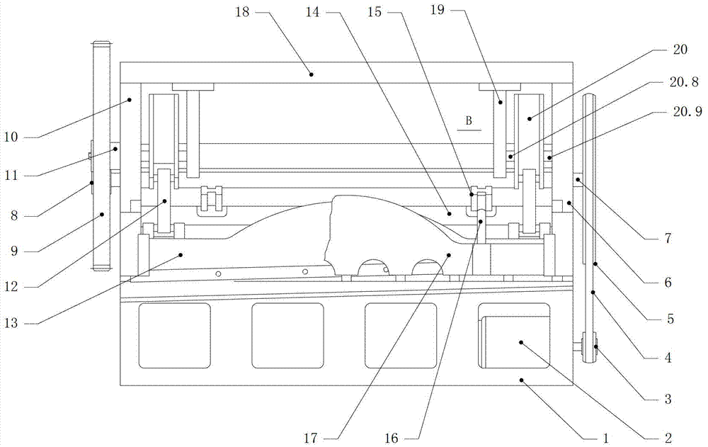
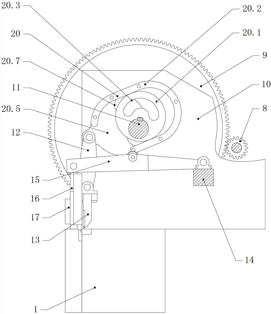
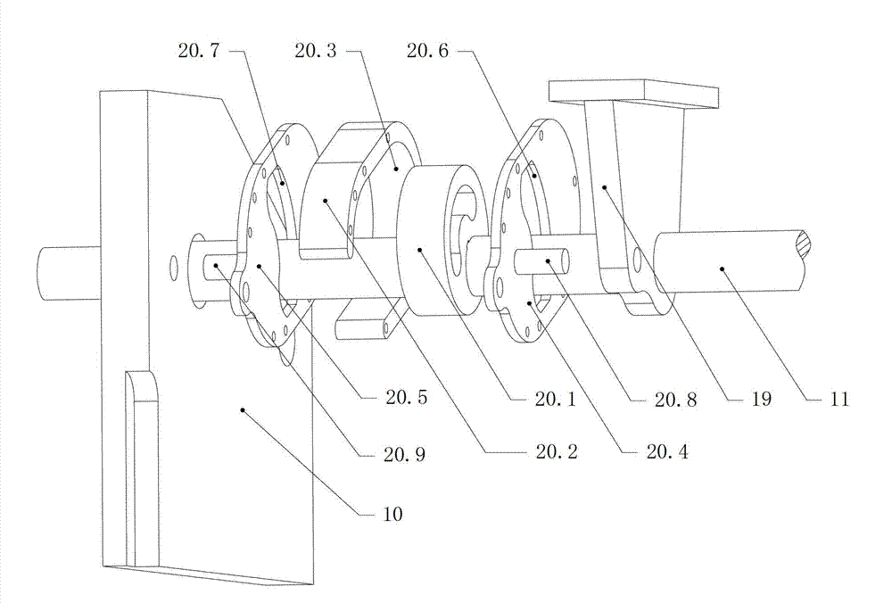
[0019] The specific embodiment of the present invention is as shown in accompanying drawing, is made of base 1, motor 2, small pulley 3, belt 4, large pulley 5, side support 16, power transmission shaft 7, pinion 8, bull gear 9, side support II10, main shaft 11, connecting rod 12, cutter 13, beam 14, support rod 15, pressing guide rod 16, pressing frame 17; the motor 2 is installed and fixed on the side of the base 1; the small pulley 3 and the motor 2 The output ends are fixed together; the transmission shaft 7 is installed on the side bracket I6 and the side bracket II10 through bearings, one end of which is fixed with the center of the large pulley 5, and the other end is fixed with the center of the pinion 8; the large pulley 5 passes through The belt 4 is connected with the small pulley 3; one end of the main shaft 11 is installed on the side bracket II10 through a bearing, and is fixed together with the center of the large gear 9, and the other end is installed on the sid...


PUM


Abstract

The invention relates to a mechanical plate shearing machine, in particular to a mechanical plate shearing machine utilizing a swing guide rod mechanism. The structure is that a cover plate is fixedly installed at the upper end of a lateral support I and a lateral support II of the plate shearing machine. T-shaped supports are symmetrically installed at two ends on the lower side of the cover plate, the upper ends of the T-shaped supports are fixed with the cover plate, and the lower ends of the T-shaped supports are sleeved on two sides of a spindle in empty mode. Execution mechanisms are symmetrically installed on the spindle section between the lateral support I and one T-shaped support and between the lateral support II and the other T-shaped support. The mechanical plate shearing machine has the advantages of being novel in structure, convenient to modify, low in cost, safe, good in economy and safety and the like, thereby being a novel mechanical plate shearing machine integrating economy and practicability.

Description

technical field [0001] The mechanical shearing machine of the present invention relates to a mechanical shearing machine utilizing a swing guide rod mechanism. Background technique [0002] The current mechanical shearing machine uses a centering crank slider mechanism as an actuator, the main shaft drives the eccentric wheel to rotate, and the connecting rod drives the cutter to perform shearing motion. Although the structure of the centering crank slider mechanism is simple and the manufacturing cost is low, the speed curve of the centering crank slider mechanism is close to a sinusoidal curve. When driving the oblique blade cutter to shear the plate, the speed changes greatly at different positions, and the quality of the incision is not uniform. It is often necessary to increase the process to process the incision, thereby greatly increasing the production cost; in addition, the centering crank slider mechanism has no quick return characteristic, and the available stroke...

Claims


Application Information

Patent Timeline
Patent Type & Authority Patents(China)
IPC IPC(8): B23D15/12
Inventor 张明恒郑雨周俊姚宝珍
Owner DALIAN UNIV OF TECH
Why Eureka
Try Eureka