Valve device

A valve device, equipped with technology, applied in the direction of valve device, valve operation/release device, fluid pressure actuation device, etc., to achieve the effect of reliable operability

Inactive Publication Date: 2015-05-06
FESTO AG & CO KG
View PDF5 Cites 0 Cited by
  • Summary
  • Abstract
  • Description
  • Claims
  • Application Information

AI Technical Summary

Problems solved by technology

[0004] If in the known valve arrangement not only the rotational actuation of the actuation lever but also its rotational actuation is to be ensured, this is only possible when the safety cover is removed

Method used


Image

  • Valve device
  • Valve device
  • Valve device

Examples


Embodiment Construction

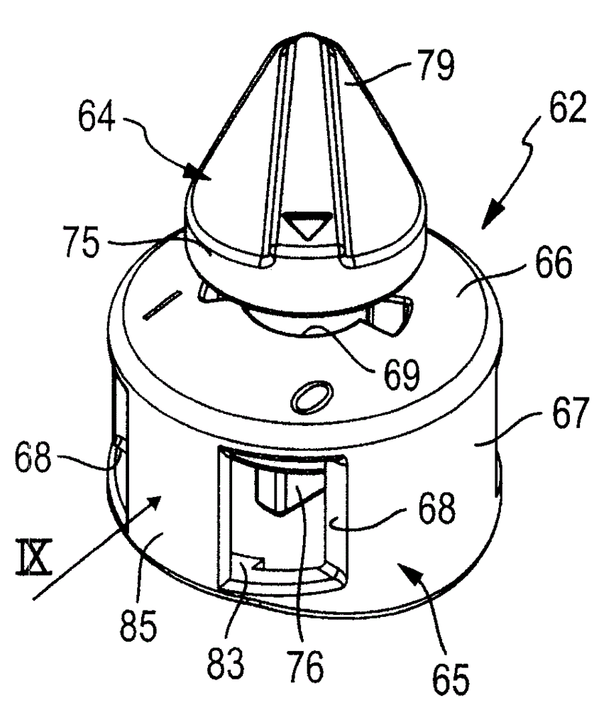
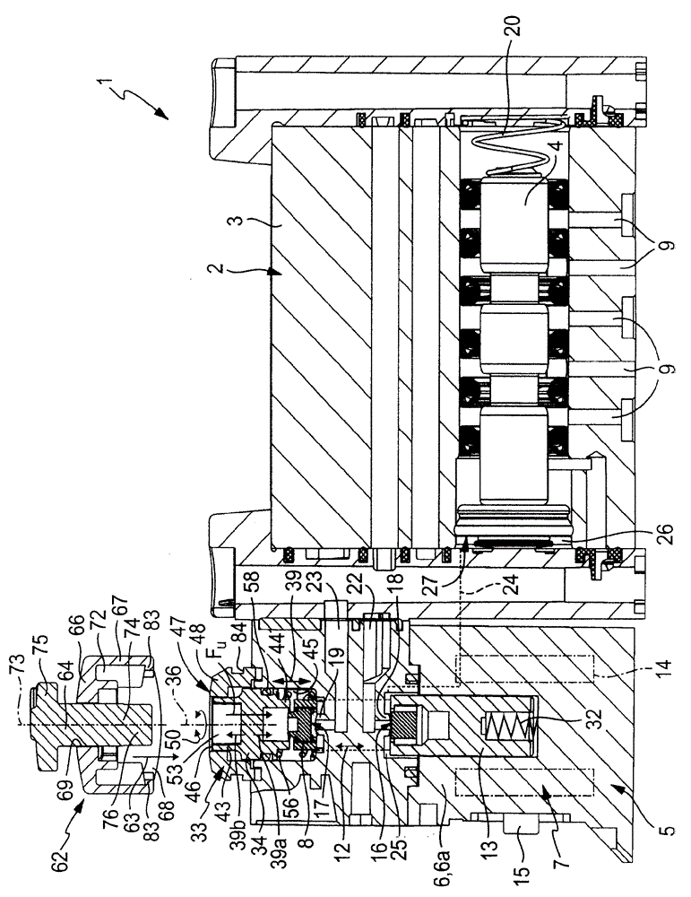
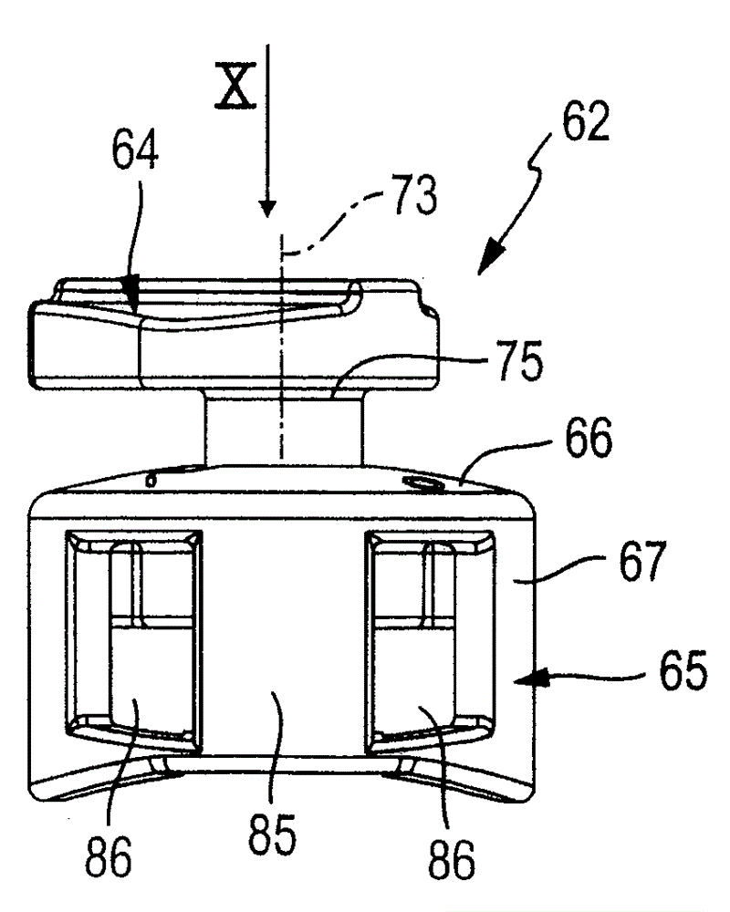
[0034] figure 1 and 2 A valve arrangement 1 of the type according to the invention is described, which is formed, for example, by a pilot-controlled multi-way valve. The valve device 1 comprises an indirectly electrically actuatable valve called main valve 2 below, which has a main valve housing 3 in which a valve plate (Ventilschieber) switchable between different switching positions (Schaltstellung) is arranged. )4. Depending on the switch position, the valve plate 4 can interconnect and separate various main valve passages 9 in different patterns to allow or prevent a certain fluid flow.

[0035] Below the main valve channel 9 there are preferably a supply channel (Speisekanal) which can be connected to a pressure source, at least one unloading channel which can be connected to a pressure reduction (Drucksenke) (eg atmosphere) and at least one which can be connected to a user to be actuated. a working channel. The at least one working channel can then be connected to th...


PUM


Abstract

Valve device (1) which has a supplementary manual actuating device (33). The supplementary manual actuating device (33) has an actuating tappet (34) with an actuating end section (43) and can firstly be moved between a basic position and a working position by way of a displacement movement (39) and can secondly be locked in the working position by means of a rotational movement (50). Furthermore, there is an additional actuating unit (62) which can be mounted on the supplementary manual actuating device (33) and which makes it possible to bring about both the displacement movement (39) and the rotational movement (50) of the actuating tappet (34) purely manually without tools.

Description

technical field [0001] The invention relates to a valve device (Ventileinrichtung) with a valve actuatable by an electric actuation, which valve is equipped with a manual auxiliary actuation device for manual actuation, which has a housing part which is movably arranged on the valve device An actuating lever in which the actuating lever has an actuating end section accessible from outside the housing part and the actuating lever can be moved between an unactuated base position and an actuated working position by means of a translational movement (Verschiebebewegung) of the actuating end section on the one hand switch between them and on the other hand can be releasably locked in the working position by the rotary movement of the operating end section; and with an additional operating unit with a manually actuatable additional operating element, which when occupying the use position The bottom can be mounted or arranged outside the housing part in such a way that the additional...

Claims


Application Information

Patent Timeline
Patent Type & Authority Patents(China)
IPC IPC(8): F16K31/10F15B13/10
CPCF16K31/426
Inventor J.布伦纳
Owner FESTO AG & CO KG
Why Eureka
Try Eureka