Battery power equalization circuit

A technology for balancing circuits and batteries, which is applied to battery circuit devices, circuit devices, current collectors, etc. It can solve the problems of difficult control of battery equalizers, slow equalization speed, and low equalization accuracy, achieving shortened equalization time, high equalization accuracy, and Improve the effect of balancing speed and efficiency

Active Publication Date: 2013-08-28
CHERY AUTOMOBILE CO LTD
View PDF3 Cites 14 Cited by
  • Summary
  • Abstract
  • Description
  • Claims
  • Application Information

AI Technical Summary

Problems solved by technology

However, this kind of battery equalizer is not easy to control, and there are still problems such as low equalization accuracy, slow equalization speed and high cost.

Method used


Image

  • Battery power equalization circuit
  • Battery power equalization circuit
  • Battery power equalization circuit

Examples


Embodiment 1

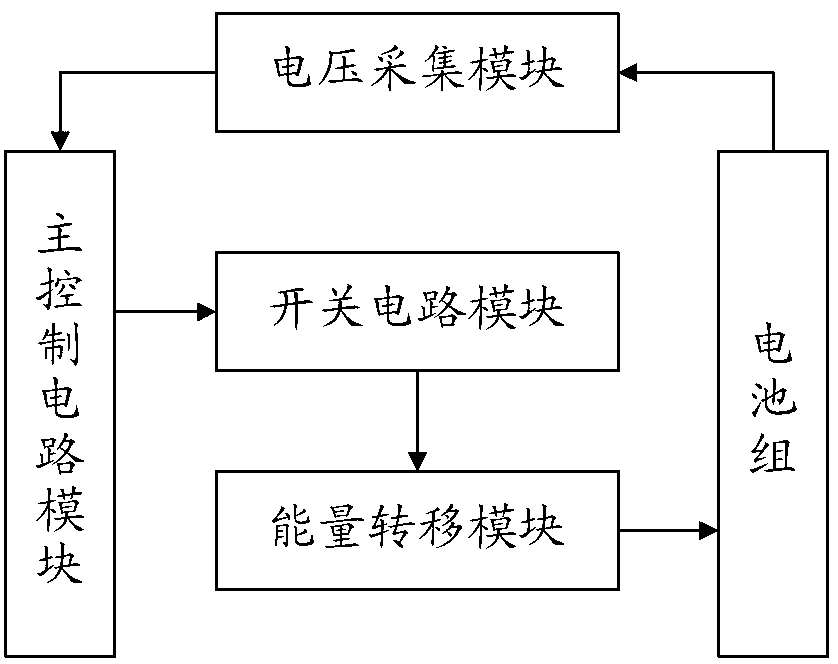
[0040] like figure 1 As shown, the present invention provides a battery power balance circuit, including: a battery pack, a voltage acquisition module, a switch circuit module, an energy transfer module and a main control circuit module.

[0041] The battery pack includes a plurality of series-connected battery sub-packs, each battery sub-pack includes a plurality of series-connected batteries.

[0042] The voltage acquisition module adopts a plurality of them, the number of which is equal to the total number of all batteries in the battery pack, and is used for real-time acquisition of voltage signals at both ends of each battery, and sending the voltage signals to the main control circuit module.

[0043] The switch circuit module includes a plurality of switches in the group and a plurality of driving circuits respectively used to drive the corresponding switches in the group, the number of the switches in the group is twice to four times the total number of all batteries i...

Embodiment 2

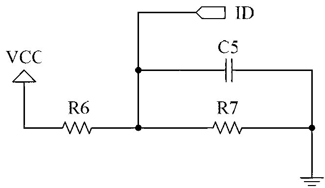
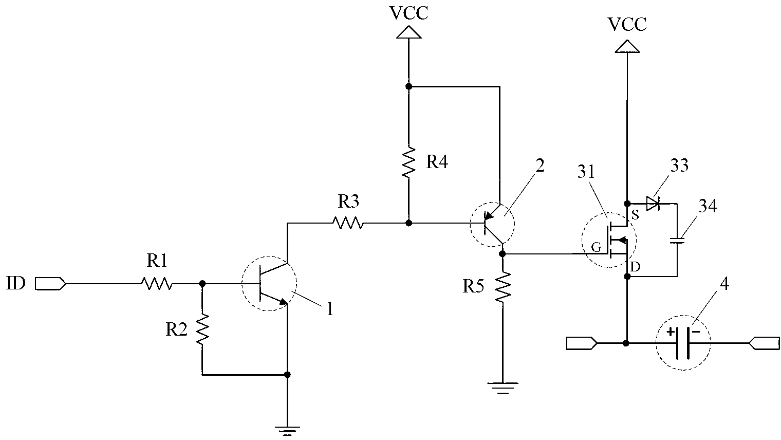
[0057] This embodiment will introduce in detail the circuit structure and connection relationship of the voltage acquisition module, the switch circuit module and the energy transfer module in the battery power balance circuit of the present invention in combination with a specific schematic diagram of the circuit connection relationship.

[0058] like figure 2 As shown, the voltage acquisition module includes a resistor R6, a resistor R7 and a capacitor C5; one end of the resistor R6 is connected to a battery, and the other end is connected to a resistor R7; one end of the resistor R7 is connected to the resistor R6 and the main control circuit respectively. The modules are connected, and the other end is grounded; the capacitor C5 is connected in parallel with both ends of the resistor R7. The voltage collection module is used to collect voltage signals at both ends of the battery in real time, and send the voltage signals to the main control circuit module ID.

[0059] Th...

Embodiment 3

[0064] This embodiment will use a specific example to describe in detail the circuit connection relationship between the battery, the switch circuit module and the energy transfer module in the battery power balance circuit, and the working principle of the battery power balance circuit.

[0065] like Figure 5 As shown, the battery power balance circuit includes 2 battery subgroups, respectively the first battery subgroup and the second battery subgroup, each battery subgroup includes 2 batteries, wherein the first battery subgroup includes batteries V1 and The battery V2, the second battery subgroup includes a battery V3 and a battery V4.

[0066] For the convenience of description, in this embodiment, the N-channel enhancement MOS transistor is represented by an NMOS transistor (in Figure 5It is only represented by N), and the P-channel enhancement MOS transistor is represented by a PMOS transistor (in Figure 5 Indicated by P only).

[0067] The switch circuit module i...


PUM


Abstract

The invention provides a battery power equalization circuit which comprises battery packs, a voltage acquisition module, a switching circuit module, power transferring modules and a main control circuit module, wherein the switching circuit module comprises a plurality of group-inner switches and a plurality of driving circuit used for respectively driving the corresponding group-inner switches; the main control circuit module is used for judging whether powers among batteries are equalized according to voltage signals at two ends of each battery; and if not, sending control signals are to the corresponding driving circuits in the switching circuit module, so that the driving circuits can control the corresponding group-inner switches to be conducted/cut off. Therefore, the power equalization among all the battery packs is realized firstly via the two groups of power transferring modules arranged in parallel; and then the power equalization among the batteries in each battery pack is realized respectively via the two groups of power transferring modules arranged in parallel. As a result, the power equalization among all the batteries is realized. The battery power equalization circuit is simple to control, high in equalization precision and rapid in speed.

Description

technical field [0001] The invention relates to the technical field of batteries, in particular to a battery power balancing circuit. Background technique [0002] Because rechargeable batteries have better cost performance, they are widely used in various types of electronic products, such as in electric vehicles. However, no matter whether it is a lithium rechargeable battery, a lead-acid rechargeable battery or a nickel-metal hydride rechargeable battery, due to the limitation of the process conditions, there are certain differences between each battery, and for the battery pack used in series, as the series battery pack The increase in the number of charge and discharge times, the aging degree and temperature of each battery in the series battery pack are different, so that the state of each battery may be different, resulting in a gradual increase in the voltage difference between the batteries, resulting in the occurrence of power imbalance between the batteries. Equi...

Claims


Application Information

Patent Timeline
Patent Type & Authority Applications(China)
IPC IPC(8): H02J7/00
Inventor 邓飞贺朱得亚
Owner CHERY AUTOMOBILE CO LTD
Why Eureka
Try Eureka