Wedge side flanging device and cold stamping die

A cold stamping and rollover technology, applied in the field of manufacturing, can solve the problem that the inclined wedge rollover mechanism cannot meet the side flanging manufacturing of the side flanges of beam parts, and achieves a convenient follow-up maintenance, compact structure and simple manufacturing process. Effect

Active Publication Date: 2013-09-04
CHERY AUTOMOBILE CO LTD
View PDF8 Cites 7 Cited by
  • Summary
  • Abstract
  • Description
  • Claims
  • Application Information

AI Technical Summary

Problems solved by technology

[0005] In order to solve the problem that the oblique wedge rollover mechanism in the prior art cannot satisfy the rollover manufacturing of the side flanges of beam parts, the embodiment of the present invention provides a pulling wedge rollover device and a cold stamping die

Method used


Image

  • Wedge side flanging device and cold stamping die
  • Wedge side flanging device and cold stamping die
  • Wedge side flanging device and cold stamping die

Examples


Embodiment 1

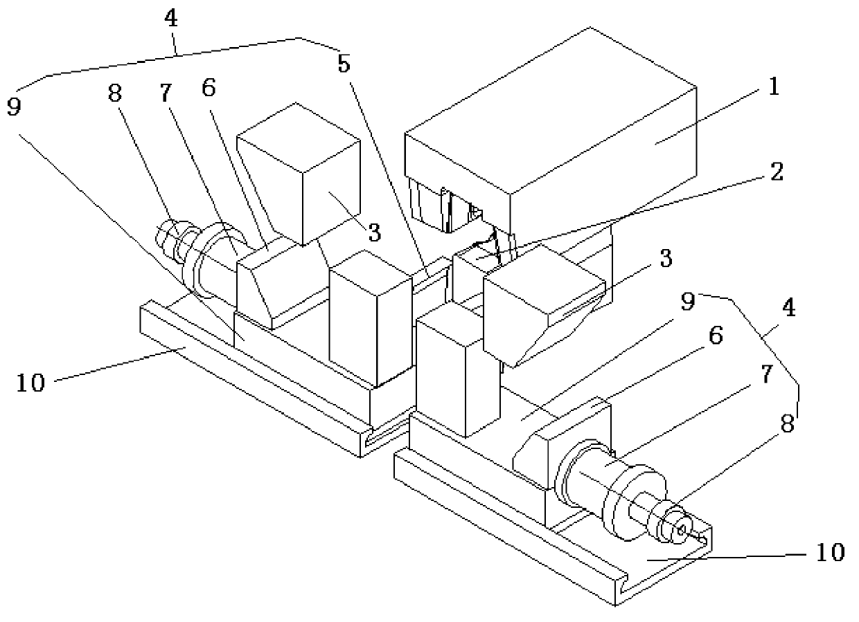
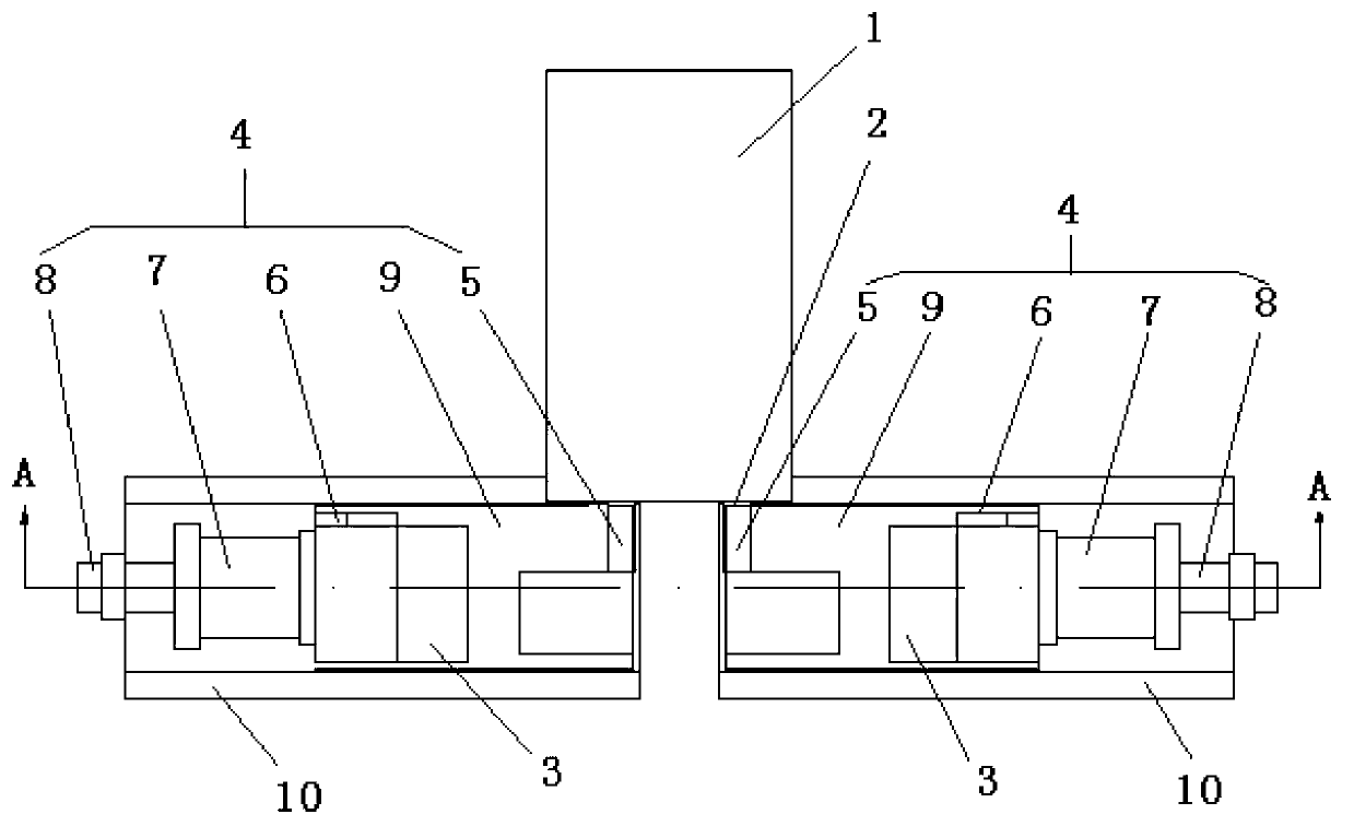
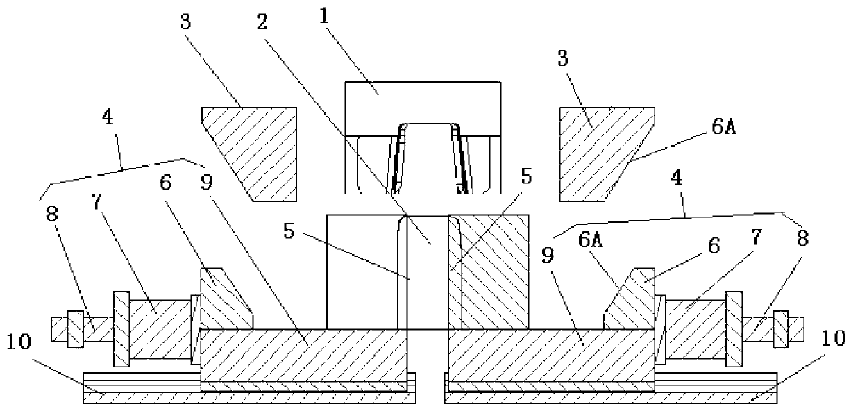
[0026] like Figure 1-3 As shown, this embodiment provides a pull wedge rollover device, and this embodiment uses figure 1 To illustrate mainly, the pull wedge rollover device is fixed between the upper mold body and the lower mold body, and the pull wedge rollover device includes a binder plate 1, a knife insert 3, a lower mold 2, a flanging mechanism 4 and Chute 10, the binder plate 1 is fixed on the upper mold body, the inserting knife 3, the flanging mechanism 4 and the chute 10 are all symmetrical structures, and they are all opposite to the binder plate 1 is symmetrical, the insertion knife 3 is fixed on the upper mold base, the lower mold 2 and the flanging mechanism 4 are fixed on the lower mold body, the flanging mechanism 4 includes a driving part and a flanging knife block 5, The flanging knife block 5 is arranged under the binder plate 1, the insertion knife 3 and the driving part are arranged on the outside of the binder plate 1, and the driving part slides relat...

Embodiment 2

[0034] On the other hand, see Figure 1-3 , the embodiment of the present invention also provides a cold stamping die, the cold stamping die includes an upper die, an upper die body, an upper die seat, a lower die body and a pull wedge rollover device, and the pull wedge rollover device is fixed on Between the upper mold body and the lower mold body, the pull wedge rollover device includes a binder plate 1, a slotting knife 3, a lower mold 2, a flanging mechanism 4 and a chute 10, and the binder plate 1 is fixed on the On the upper mold body, the insertion knife 3, the flanging mechanism 4 and the chute 10 are all symmetrical structures, and they are all symmetrical with respect to the binder plate 1, and the insertion knife 3 is fixed on the upper mold base. The lower mold 2 and the flanging mechanism 4 are fixed on the lower mold body, the flanging mechanism 4 includes a driving part and a flanging knife block 5, and the flanging knife block 5 is arranged on the binder plate...


PUM


Abstract

The invention discloses a wedge side flanging device and a cold stamping die and belongs to the field of manufacturing. The wedge side flanging device is fixed between an upper die body and a lower die body and comprises a pressing plate, slotting tools, a lower die, flanging mechanisms and slide grooves. The pressing plate is fixed on the upper die body. Each slotting tool is fixed on an upper die seat. The lower die and the flanging mechanisms are fixed on the lower die body. Each flanging mechanism comprises a drive part and a flanging cutter block, and the cutter block is disposed below the pressing plate. Each slotting tool and each drive part are disposed on each of the outer sides of the pressing plate. By the wedge side flanging device, side flanging of side flanges of beam parts can be completed conveniently. In addition the wedge side flanging device has the advantages that the wedge side flanging device is exquisite in structure, simple in manufacturing process and high in practicality, subsequent maintenance is facilitated, and subsequent maintenance cost of dies can be lowered effectively.

Description

technical field [0001] The invention relates to the field of manufacturing, in particular to a pull wedge rollover device and a cold stamping die. Background technique [0002] In today's increasingly fierce market competition, all enterprises are faced with the problem of how to survive and develop sustainably, and adopting technological innovation and equipment improvement and upgrading to reduce production costs and improve work efficiency is the most direct and effective development direction. [0003] In the process of new product development, the cost of mold development accounts for a relatively large proportion. How to save the cost of mold development to the greatest extent is an important research topic for OEMs and mold manufacturers. [0004] Cold stamping die is a kind of mechanical equipment widely used in the manufacturing industry. The wedge rollover mechanism is an important part of the cold stamping die. Due to the space limitation of the installation of t...

Claims


Application Information

Patent Timeline
Patent Type & Authority Applications(China)
IPC IPC(8): B21D37/10
Inventor 宋志翔丁丽唐东胜
Owner CHERY AUTOMOBILE CO LTD
Why Eureka
Try Eureka