Automatic transmission testing system

A technology of automatic transmission and testing system, which is applied in the testing of machine/structural components, machine gear/transmission mechanism testing, vehicle testing, etc., and can solve the problem of optimal stock value deviation, poor consistency of automatic transmission actual performance, automatic transmission follow-up Use unfavorable effects and other issues to achieve the effect of small deviation

Active Publication Date: 2015-07-08
ZHEJIANG GEELY POWERTRAIN CO LTD +2
View PDF6 Cites 0 Cited by
  • Summary
  • Abstract
  • Description
  • Claims
  • Application Information

AI Technical Summary

Problems solved by technology

The oil injection accuracy of the existing oil injection device on the automatic transmission test line is generally ±100ml, and the cycle exchange process between the ATF oil injected in the automatic transmission and the external cooler and other equipment during the testing process will also be packaged off the assembly line after passing the test The actual stock of ATF oil in the automatic transmission has a certain influence
Therefore, the actual stock of ATF oil in a small number of qualified and packaged automatic transmissions put into storage may deviate from the qualified range, or although it is in the qualified range, there is a relatively large deviation from the optimal stock value. The actual performance consistency of automatic transmissions in the library is poor, and the performance of a small number of automatic transmissions deviates greatly from the best performance, thus adversely affecting the subsequent use of automatic transmissions (including the use in automobile installation production and consumer use)

Method used


Image

  • Automatic transmission testing system

Examples


Embodiment Construction

[0011] The technical solutions of the present invention will be further specifically described below through the embodiments and in conjunction with the accompanying drawings.

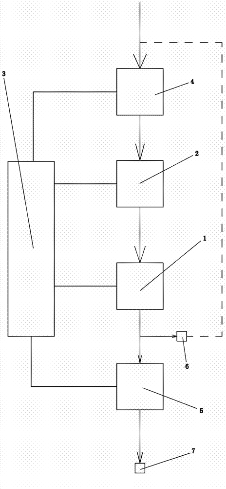
[0012] Such as figure 1 As shown, the present invention includes a detection device 1, an oil injection device 2 located at the front end of the detection device 1, a detection control device 3, a first weighing device 4 located at the front end of the oil injection device 2 and a second weighing device located at the rear end of the detection device 1. Heavy device 5. The detection device 1, the oil injection device 2, the first weighing device 4 and the second weighing device 5 are all electrically connected to the detection control device, and the weighing accuracy of the first weighing device 4 and the second weighing device 5 are both ±20 gram. The oil injection device 2 is equipped with a metering pump, and the metering pump is a hydraulic diaphragm metering pump or an electromagnetic diaphragm...


PUM


Abstract

The invention discloses an automatic transmission testing system, which comprises a detection device, an oil injection device, a detection control device, a first weighing device and a second weighing device, wherein the oil injection device is arranged at the front end of the detection device; the first weighing device is arranged at the front end of the oil injection device; the second weighing device is arranged at the back end of the detection device; the detection device, the oil injection device, the first weighing device and the second weighing device are all electrically connected with the detection control device; the weighing accuracies of the first weighing device and the second weighing are + / -20g; a metering pump is arranged on the oil injection device; the metering pump is a hydraulic diaphragm metering pump or an electromagnetic diaphragm metering pump, and is used for injecting oil into an automatic transmission quantitatively; the detection control device is provided with an acousto-optic alarm device; and the acousto-optic alarm device can be used for transmitting a corresponding acousto-optic alarm signal according to whether a detected automatic transmission is qualified or not. The automatic transmission testing system has the advantages that during packaging and warehousing, the deviation between practical retained ATF (Automatic Transmission Fluid) and an optical retaining amount in the automatic transmission is small, and the automatic transmission has high practical performance and high consistence.

Description

technical field [0001] The invention relates to a transmission performance testing device, in particular to an automatic transmission performance testing device. Background technique [0002] Automatic transmissions rely on ATF oil as the basic medium to realize functions such as hydraulic transmission, clutch control, hydraulic unit control (HCU), lubrication, and cooling. Quantity is also strictly controlled. Too much or too little ATF oil in the automatic transmission will have an adverse effect on the performance of the automatic transmission. The automatic transmission test line is the final testing equipment before the automatic transmission leaves the factory. The existing automatic transmission test system usually includes two major components: oil injection and detection. The automatic transmission that passes the performance test is usually packaged with the ATF oil injected into the automatic transmission during the test, and is put into storage. The automatic t...

Claims


Application Information

Patent Timeline
Patent Type & Authority Patents(China)
IPC IPC(8): G01M17/007G01M13/02
Inventor 王二朋王瑞平
Owner ZHEJIANG GEELY POWERTRAIN CO LTD
Why Eureka
Try Eureka