Unlock instant, AI-driven research and patent intelligence for your innovation.

Heat transfer

A thermal energy and thermal contact technology, applied in heat exchange equipment, heat exchanger types, indirect heat exchangers, etc., can solve problems such as low heat transfer rate and inability to adjust heat transfer efficiency

Inactive Publication Date: 2013-10-23
THE UNIV OF SYDNEY
View PDF4 Cites 4 Cited by
  • Summary
  • Abstract
  • Description
  • Claims
  • Application Information

AI Technical Summary

Problems solved by technology

[0007] Existing methods and devices for heat transfer have inefficiencies that limit the rate of heat transfer
In addition, existing methods and devices cannot adjust the efficiency of heat transfer

Method used


Image

  • Heat transfer
  • Heat transfer
  • Heat transfer

Examples


Embodiment 1

[0228] Example 1: Endothermic

[0229] Figure 11 The apparatus 110 for heat transfer used in Example 1 is shown. The device 110 includes a base portion 111 and an array of eight disks 112 in thermal contact with the base portion 111 . The base portion 111 is made of aluminum and has a length of 5 cm, a width of 5 cm and a height of 2 cm. Each disk 112 is made of aluminum and has a radius of 20 mm and a thickness of 2 mm. The base portion 111 has a series of slots spaced apart to accommodate the disc 112 . The disks 112 are fixedly mounted to the rotatable rod 13 such that rotation of the rod 113 causes each disk 112 to rotate in a slot in the base portion 111 . As the disk 112 rotates, thermal contact between the base portion 111 and the disk 112 is maintained.

[0230] In a first experiment, device 110 was heated to above 54° C. on a hot plate. After heating, the device 110 is removed from the hot plate and placed in a heat shield to reduce heat loss from the surface o...

Embodiment 2

[0232] Figure 12 The temperature of the device 11 is shown as a function of time with and without the disk 112 rotating. In both cases, the temperature decay is exponential, with a characteristic time τ; shorter times τ correspond to more efficient cooling. Spinning the disk 112 at 5 Hz reduces the cooling time of the device 110 by about 50% (ie, improves cooling efficiency) compared to the cooling time without the disk 112 rotating. Example 2: Tubular Heat Exchanger

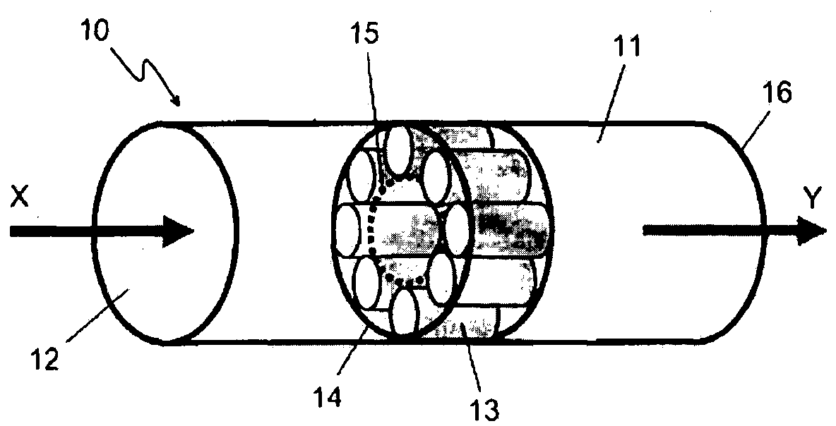
[0233] FIG. 13( a ) shows a disassembled device 130 for heat transfer used in Example 2. FIG. Device 130 is a tube heat exchanger for transferring heat between a first material inside the heat exchanger and a second material outside the heat exchanger.

[0234] The device 130 includes a tube 131 and nine rollers 132 . The tube 131 is made of steel and has a length of 250 mm, an outer radius of 25 mm and a wall thickness of 2 mm. Each roller 132 is a hollow steel cylinder with a length of 24 mm, an outer ra...


PUM

PropertyMeasurementUnit
diameteraaaaaaaaaa
diameteraaaaaaaaaa
diameteraaaaaaaaaa

Abstract

The invention relates to a method for transferring heat between a first material having a first temperature and a second material having a second temperature, wherein said first temperature is greater than said second temperature, said method comprising providing one or more rotatable elements, disposing said one or more rotatable elements such that a heat transfer portion thereof is thermally contactable with both said first material and said second material on rotation of said one or more rotatable elements, and rotating said one or more rotatable elements, whereby heat is transferred from said first material to said heat transfer portion and from said heat transfer portion to said second material.

Description

technical field [0001] The present invention relates to methods and apparatus for heat transfer. [0002] related application [0003] This application claims priority from Australian Provisional Patent Application No. 2010904807, the entire contents of which are hereby incorporated by cross reference. Background technique [0004] Any discussion of the background art in this specification should neither be considered as an admission that the background art is prior art, nor should it be considered as an admission that the background art is generally known in the field or forms part of the common general knowledge in the field. [0005] Thermal energy can be transferred from one material to another through radiation, conduction and convection. The methods and apparatus for transferring heat can be used in a range of applications for increasing or decreasing the temperature of a material. These applications include mechanical engineering, electrical engineering, aeronautic...

Claims


Application Information

Patent Timeline
Patent Type & Authority Applications(China)
IPC IPC(8): F28D19/04F28F5/00
CPCF28D19/00F28F2255/02B23P15/26F28D19/045F28F7/00F28D19/041Y10T29/4935
Inventor 伊泰·埃纳弗皮埃尔·罗尼翁
Owner THE UNIV OF SYDNEY