Fire-protection emergency sign lamp

A technology for fire emergency and lamps, which is applied to the layout of electric lamp circuits, lighting devices, light sources, etc. It can solve the problems of failure to meet requirements, electric leakage and electric shock, and inability to dynamically adjust the direction of escape, so as to reduce the possibility of electric leakage and injury accidents , The effect of equipment safety and reliability

Active Publication Date: 2013-11-27
江苏银佳电子设备有限公司
View PDF4 Cites 8 Cited by
  • Summary
  • Abstract
  • Description
  • Claims
  • Application Information

AI Technical Summary

Problems solved by technology

[0002] Fire emergency sign lights provide escape routes for people to escape when a fire occurs. However, traditional evacuation emergency sign lights exist as isolated monomers in buildings, and cannot respond to changes in the fire scene, let alone dynamically adjust the escape direction. Instructions, making it difficult to escape from the scene
The traditional emergency sign lamps are powered by AC220V. When a fire breaks out, firefighters are prone to electric leakage and electric shock when they extinguish the fire.
In addition, there is a serious hysteresis in the daily maintenance and repair of traditional emergency sign lights. The main function of emergency sign lights is to start an emergency in the event of a fire, and the key to starting an emergency is whether the battery charge and discharge work normally.
Relying on manpower maintenance and inspection, product problems cannot be found in time, and its reaction is that in the event of a fire, it often brings many blind spots to the escape and evacuation instructions of the building
Such application status can no longer meet the requirements of modern large buildings

Method used


Image

  • Fire-protection emergency sign lamp
  • Fire-protection emergency sign lamp
  • Fire-protection emergency sign lamp

Examples


Embodiment Construction

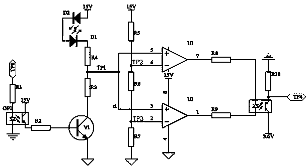
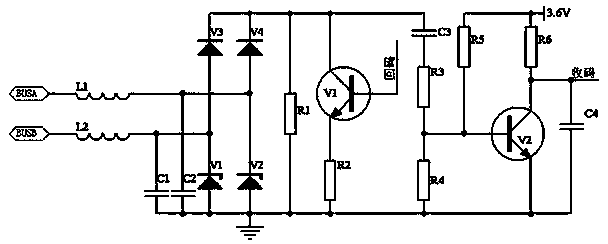
[0020] The invention discloses a fire emergency sign lamp, which comprises a DC power supply module, a step-down circuit module, an LED load module, a second communication bus module, an MCU control module, an LED fault detection module, and an emergency lighting controller;

[0021] The DC module is connected to the LED load module through the step-down circuit module, the output end of the LED load module is connected to the input end of the MCU control module and the input end of the LED fault detection module respectively, and the output end of the LED fault detection module is connected to the MCU control module. connected, the MCU control module is connected with the second communication bus module, and the second communication bus module is connected with the emergency lighting controller;

[0022] The DC power output by the DC power supply module is stepped down by the step-down circuit module to supply power to the LED load module; the LED fault detection module de...


PUM


Abstract

The invention discloses a fire-protection emergency sign lamp. The fire-protection emergency sign lamp comprises a direct current power supply module, a buck circuit module, an LED load module, a communication two-bus module, an MCU control module, an LED fault detection module and an emergency lighting controller; the direct current power supply module is connected with the LED load module through the buck circuit module; the output end of the LED load module is connected with the input end of the MCU control module and the input end of the LED fault detection module respectively; the output end of the LED fault detection module is connected with the MCU control module; the MCU control module is connected with the communication two-bus module; and the communication two-bus module is connected with the emergency lighting controller. The fire-protection emergency sign lamp provided by the invention is advantageous in safety, reliability and reduction of the possibility of electric leakage-caused wounding, and can indicate escape routes according to on-site actual situations, and more effectively realize the effect of fire-protection emergency signs.

Description

technical field [0001] The invention discloses a fire emergency sign lamp, in particular to a fire emergency sign lamp with centralized power supply and centralized control, which belongs to the field of emergency sign lamps. Background technique [0002] Fire emergency sign lights provide escape routes for people to escape when a fire occurs. However, traditional evacuation emergency sign lights exist as isolated monomers in buildings, and cannot respond to changes in the fire scene, let alone dynamically adjust the escape direction. Instructions will bring difficulties to escape from the scene. The traditional emergency sign lamps are powered by AC220V. When a fire breaks out, firefighters are prone to electric leakage and electric shock when they extinguish the fire. In addition, there is a serious hysteresis in the daily maintenance and repair of traditional emergency sign lights. The main function of emergency sign lights is to start an emergency in case of fire, and t...

Claims


Application Information

Patent Timeline
Patent Type & Authority Applications(China)
IPC IPC(8): H05B37/02
Inventor 檀三强肖练朱忠伟季程荣宁振坤
Owner 江苏银佳电子设备有限公司
Why Eureka
Try Eureka