Heating modules for exhaust gas cleaning systems

A heating module, exhaust gas purification technology, applied in mechanical equipment, exhaust gas treatment, gas passages, etc., can solve problems such as inability to affect the engine

Inactive Publication Date: 2018-01-05
HJS EMISSION TECH
View PDF6 Cites 0 Cited by
  • Summary
  • Abstract
  • Description
  • Claims
  • Application Information

AI Technical Summary

Problems solved by technology

In many cases, measures on the engine side cannot be influenced in the context of exhaust gas cleaning

Method used


Image

  • Heating modules for exhaust gas cleaning systems
  • Heating modules for exhaust gas cleaning systems
  • Heating modules for exhaust gas cleaning systems

Examples


Embodiment Construction

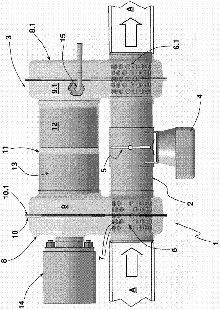
[0024] The heating module 1 of the first embodiment of the present invention is connected into an exhaust gas pipe of an exhaust gas purification device not shown in detail. The exhaust gas purification system is in turn connected to the outlet of the diesel engine as an internal combustion engine. The exhaust gas pipe connected into the heating module 1 is identified with the reference number A. The heating device 1 is passing through figure 1 The flow direction of the exhaust gas indicated by the solid line arrow in , is preceded by an exhaust gas purification device, such as a particulate filter. Preferably, the particle filter is preceded by an oxidation catalytic converter.

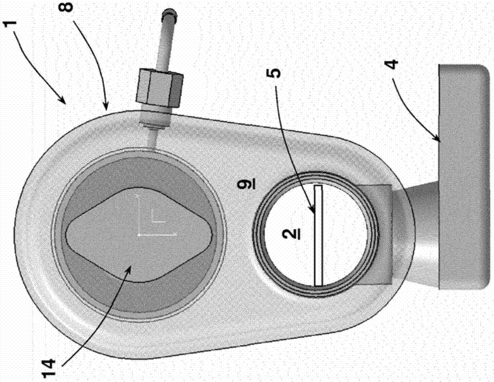
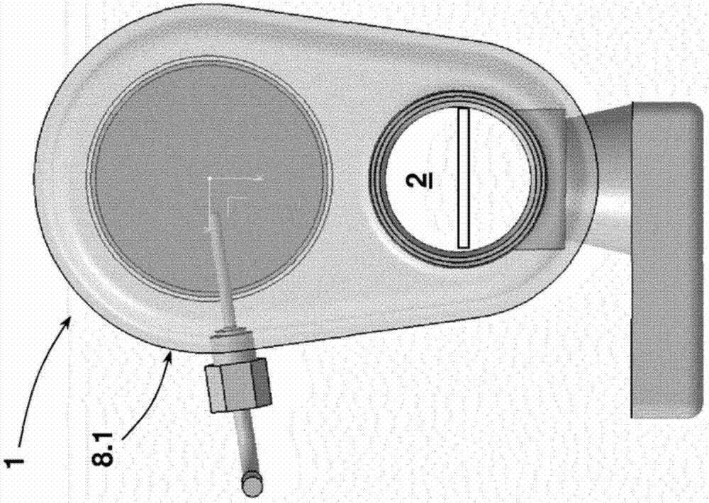
[0025] The heating module 1 according to the first embodiment of the invention has a main line 2 and a secondary line 3 . The main line 2 is part of the exhaust pipe A of the exhaust gas purification system. Exhaust gases from the diesel engine flow through the main line 2 of the heating module 1...


PUM


Abstract

The invention relates to a heating module for an exhaust gas purification system connected to an outlet of an internal combustion engine, the heating module comprising a hydrocarbon injector (14) with an oxidation catalytic converter downstream in the flow direction of the exhaust gas (12) The catalytic burner for supplying thermal energy to an exhaust gas purification device of an exhaust gas purification device. It is proposed here that the heating module (1) has a main line (2), a secondary line (3) containing a catalytic burner (12, 14) and a device for controlling the exhaust gas mass flow through the secondary line (3) (4, 5). According to a first configuration, the main line (2) has an overflow line section (6) with an overflow opening (7) in the inlet area of ​​the heating module (1), a secondary line section with an oxidation catalytic converter (12) ( 11) Between the overflow diversion chambers (8) parallel to the main line (2) of the heating module (1). According to a further design proposal, the secondary line section (3) has, on the input side and on the output side, a deflection chamber (8) protruding radially from the main line (2), with an oxidation catalytic converter (12) The secondary line section (11) runs parallel to the main line (2) of the heating module (1) between the turning chambers (8).

Description

technical field [0001] The invention relates to a heating module for an exhaust gas purification device connected to the outlet of an internal combustion engine, said heating module comprising a catalytic burner with a hydrocarbon injector with a direction of flow of the exhaust gas An oxidation catalytic converter downstream of a hydrocarbon injector for supplying thermal energy to an exhaust gas purification system of an exhaust gas purification system, wherein the heating module has a main line, a secondary line containing a catalytic burner and a secondary line for controlling the flow through the secondary A device for mass flow of exhaust gases in the pipeline. Background technique [0002] Today internal combustion engines, especially diesel engines, have devices which are inserted into the exhaust tract in order to reduce harmful or undesired emissions. Such devices may be, for example, oxidation catalysts, particle filters and / or SCR stages. Particulate filters ar...

Claims


Application Information

Patent Timeline
Patent Type & Authority Patents(China)
IPC IPC(8): F01N3/025F01N3/20
CPCF01N3/025F01N3/0256F01N3/2053F01N2240/14F01N2240/16F01N2410/00F01N2470/02F01N2610/03F01N3/20F01N3/08
Inventor B.贝尔B.莫勒K.施赖维F.诺亚克T.卡斯特纳
Owner HJS EMISSION TECH
Why Eureka
Try Eureka