Method, device and system for controlling PMSM (Permanent Magnet Synchronous Motor) to put into operation again at belt speed

A permanent magnet synchronous motor, re-input technology, applied in the control system, motor control, vector control system and other directions, can solve the problem of isolation contactor input logic without considering the re-operation, unable to ensure the stable operation of the closed control system, etc.

Active Publication Date: 2014-01-15
CSR ZHUZHOU ELECTRIC LOCOMOTIVE RES INST
View PDF2 Cites 41 Cited by
  • Summary
  • Abstract
  • Description
  • Claims
  • Application Information

AI Technical Summary

Problems solved by technology

[0016] Moreover, none of the above methods considers the problem from the perspective of the system, nor does it consider the input logic of the isolation cont

Method used


Image

  • Method, device and system for controlling PMSM (Permanent Magnet Synchronous Motor) to put into operation again at belt speed
  • Method, device and system for controlling PMSM (Permanent Magnet Synchronous Motor) to put into operation again at belt speed
  • Method, device and system for controlling PMSM (Permanent Magnet Synchronous Motor) to put into operation again at belt speed

Examples


Embodiment 1

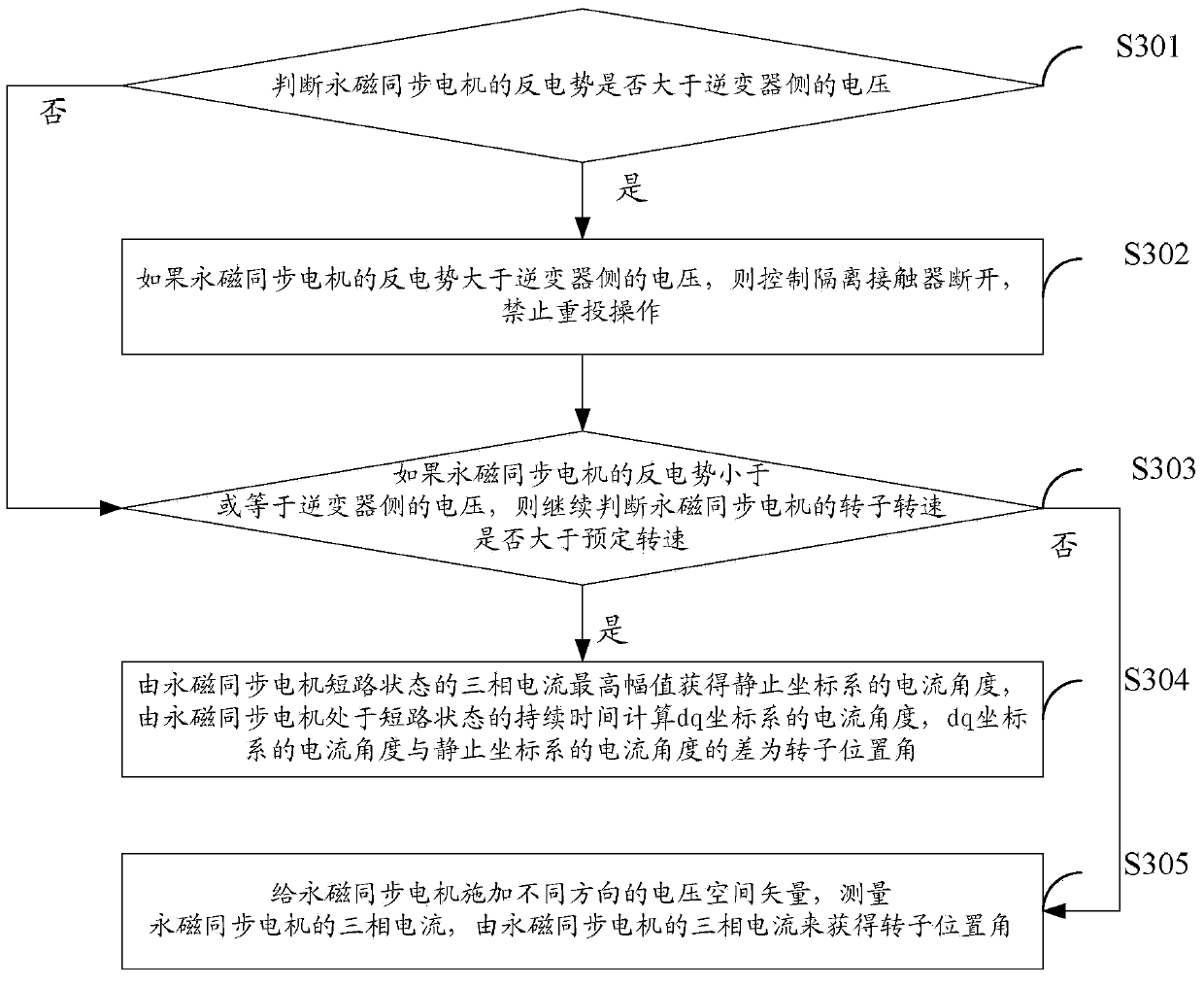
[0111] see image 3 , which is a flow chart of Embodiment 1 of the control method for re-starting the permanent magnet synchronous motor with speed provided by the present invention.

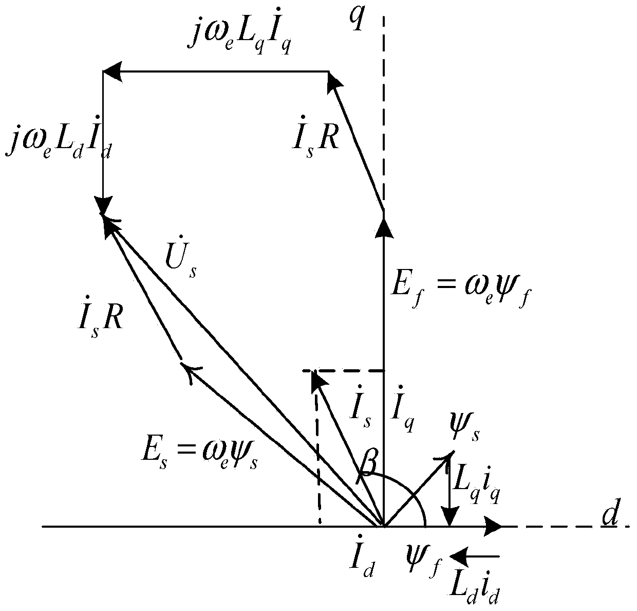
[0112] First, the working principle on which the present invention is based is introduced.

[0113] It can be seen from formula (1) that as long as the speed ω e is high enough, the back EMF E 0 will be higher than the intermediate DC side voltage U of the inverter dc , if the belt-speed re-commissioning operation is performed at this time and the isolation contactor is switched on, the PMSM will reversely charge the DC side of the inverter. The charged voltage amplitude of the capacitor on the DC side of the inverter may be higher than the safe allowable value of the capacitor, causing damage to the capacitor.

[0114] Therefore, re-injection with speed is not possible at all speeds of the PMSM, and it needs to be judged according to the rotational speed of the PMSM corresponding to the re-...

Embodiment 2

[0130] The method of obtaining the rotor position angle by using a short-circuit method provided by the present invention when the PMSM is in the medium-high speed section will be described in detail below in conjunction with the accompanying drawings.

[0131] see Figure 4 , which is a flow chart of the primary short-circuit method in the middle and high-speed section provided by the present invention.

[0132] Due to the existence of the back electromotive force when the PMSM is idling, if the three phases of the PMSM are short-circuited, the three-phase short-circuit current must contain the position information of the PMSM rotor, so the short-circuit method can be used to obtain the rotor position angle.

[0133] S401: applying a zero-voltage vector to make the permanent magnet synchronous motor in a short-circuit state;

[0134] It should be noted that there are two zero voltage vectors, one is and That is, by applying these two different zero-voltage vectors, all t...

Embodiment 3

[0154] The following introduces that the present invention uses the INFORM method to obtain the rotor position angle when it is in the low-speed stage.

[0155] see Figure 6 , which is a flow chart for calculating the rotor position angle using the INFORM method provided by the present invention.

[0156] First, the basic principle of the INFORM method is introduced: apply voltage space vectors to the motor terminals from different directions, and estimate the rotor position by measuring their different current responses.

[0157] The basic principle used is: the magnetic circuit of the motor has a salient polarity, and the inductance value of the stator winding is a function of the rotor position, so the current response generated by the voltage space vector at different positions must contain the rotor position information.

[0158] Since the applied voltage space vector is a high-frequency voltage signal, and the current response is also a high-frequency signal, the motor...


PUM


Abstract

The invention provides a method, device and system for controlling a PMSM (Permanent Magnet Synchronous Motor) to put into operation again at the belt speed. The counter EMF of the PMSM is obtained by the speed of a trailer, and is compared with the voltage on the inverter side, if the counter EMF is higher than the voltage on the inverter side, the PMSM is not allowed to be put into operation again at the belt speed, otherwise, the PMSM is put into operation again at the belt speed. When the PMSM is allowed to be put into operation again at the belt speed, a separation contactor is closed; when the PMSM is not allowed to be put into operation again at the belt speed, the separation contactor is switched off. Therefore, the method, the device and the system can be used for computing the rotor position angles through dividing the working conditions into low-speed working conditions and medium-high speed working conditions according to Omega e, and the PMSM is started through the rotor position angles; the overall control method is provided from the view of system, the PMSM at the high speed section is not allowed to be put into operation again at the belt speed, the position for the PMSM at the medium-high speed section to be put into operation again is determined through adopting a one-step short-circuit method to compute the rotor position angles, the position for the PMSM at the low speed section to be put into operation again is determined through adopting an INFORM (Indirect Flux detection by On-line Reactance Measurement) method to compute the rotor position angles.

Description

technical field [0001] The invention relates to the technical field of permanent magnet synchronous motor control, in particular to a control method, device and system for re-introduction of permanent magnet synchronous motor with speed. Background technique [0002] Permanent magnet synchronous motor (PMSM, Permanent Magnet Synchronous Motor) transmission system refers to a new type of transmission system that takes PMSM as the control object and controls the speed and torque of permanent magnet synchronous motor through frequency modulation and voltage regulation. Compared with the AC transmission system with asynchronous motor as the control system, the PMSM transmission system has a series of advantages that cannot be compared with AC motors, such as simple structure, high power density, large low-speed output torque, high efficiency, and convenient maintenance. It will replace the asynchronous motor AC drive system and become the mainstream in the future. [0003] see ...

Claims


Application Information

Patent Timeline
IPC IPC(8): H02P21/00
CPCH02P1/029H02P6/182H02P6/20H02P6/24H02P2207/05H02P21/18H02P21/22H02P21/36H02P29/10H02P27/08H02P21/24
Inventor 冯江华刘可安许峻峰尚敬文宇良何亚屏张朝阳刘雄南永辉刘华东肖磊郑汉锋
Owner CSR ZHUZHOU ELECTRIC LOCOMOTIVE RES INST
Why Eureka
Try Eureka