Shock vibration snow removal device

A technology of impact vibration and vibration device, which is applied in snow surface cleaning, construction, cleaning methods, etc. It can solve the problems of equipment personal safety threat, spring preload influence, blade damage, etc., achieve good snow removal effect and ensure safe operation , to avoid the effect of duplication of work

Active Publication Date: 2014-01-22
白山市星泰矿山机械制造有限公司
View PDF4 Cites 2 Cited by
  • Summary
  • Abstract
  • Description
  • Claims
  • Application Information

AI Technical Summary

Problems solved by technology

But this snow removal shovel has exposed the following defects in the specific application process: 1, the engine device of this snow removal shovel pushes the snow plate, but it still adopts the sanitation vehicle engine as the power source (that is, the power drive system of the sanitation vehicle needs to be modified , to provide the power source for the shock vibration device), using this connection method, it is very easy to cause problems such as vehicle performance imbalance, driving safety factor reduction, etc., which poses a great threat to equipment and personal safety; The structure is that the blade is connected to the spring through the obstacle-crossing bracket. During use, due to the long-term impact and vibration, the pre-tightening force of the spring is easily affected, so that the obstacle-crossing function is gradually lost, and the blade is easily damaged.
3. The suspension of this snow removal shovel is only a connecting plate, which alone serves the connection function with the vehicle body. During use, due to the fixed connection between the main frame and the suspension, especially when working on uneven roads, When the bracket is subjected to a large torque, the main frame is easily bent and broken, resulting in failure

Method used


Image

  • Shock vibration snow removal device
  • Shock vibration snow removal device
  • Shock vibration snow removal device

Examples


Embodiment 1

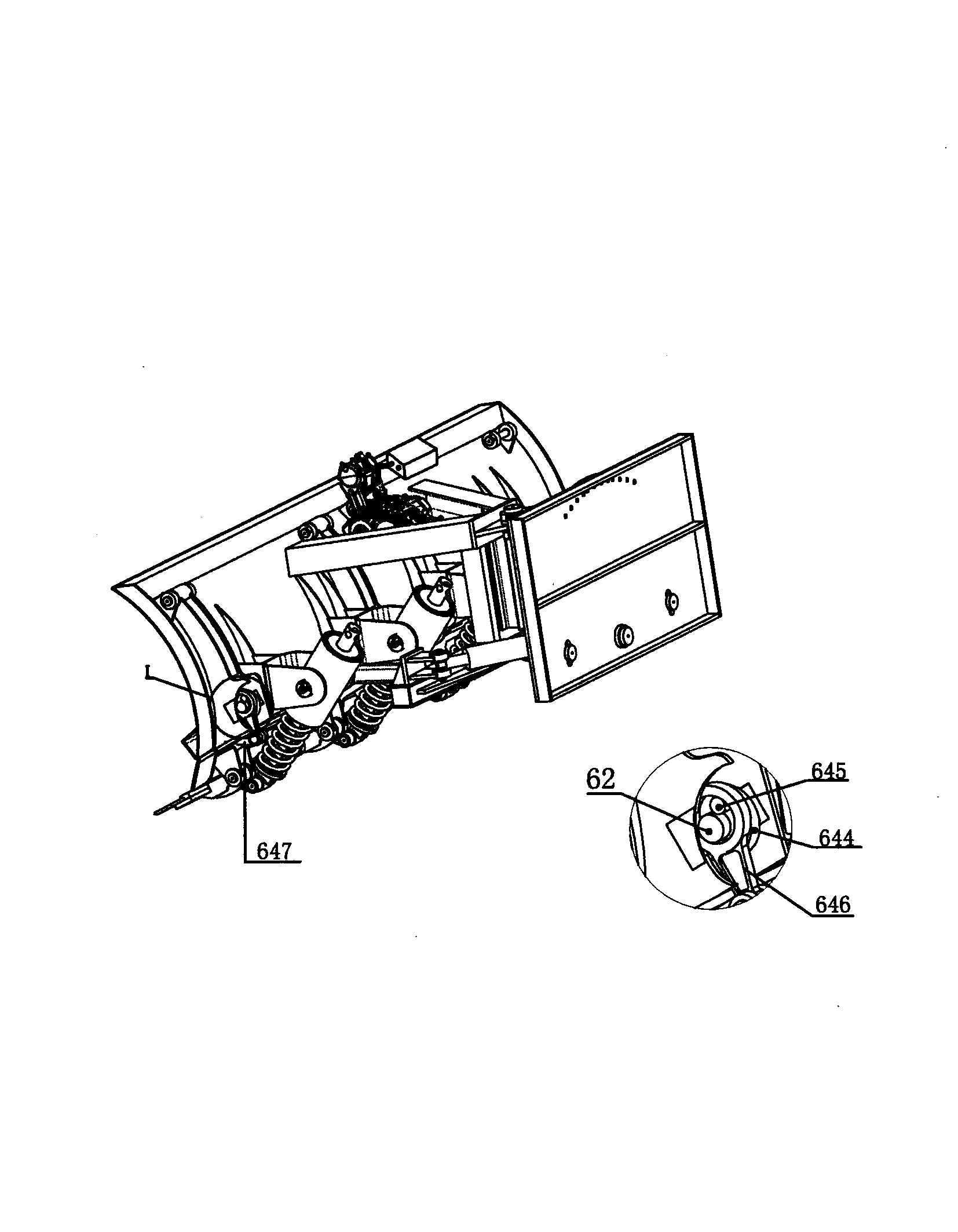
[0031] like image 3Shown, the present invention selects the structural representation of planar connecting rod type vibration mechanism; It comprises eccentric disk 644, crank shaft 645, crank connecting rod 646 and crank connecting rod seat 647, and eccentric disk 644 wears on the transmission shaft 62, and crank shaft 645 is fixed on the eccentric disc 644, one end of the crank connecting rod 646 is sleeved on the transmission shaft 62 and the crank shaft 645, and the other end is twisted on the crank connecting rod seat 647, and is matched with the crank connecting rod seat 647 in clearance, the crank is connected The rod seat 647 is fixed on the vibrating beam 63 . When the engine or the hydraulic pump drives the transmission shaft 62 to rotate, the transmission shaft 62 simultaneously drives the eccentric disc 644 and the crank shaft 645 on the eccentric disc to rotate eccentrically. Vibration provides a certain impact force to the blade 33 to realize vibration snow rem...

Embodiment 2

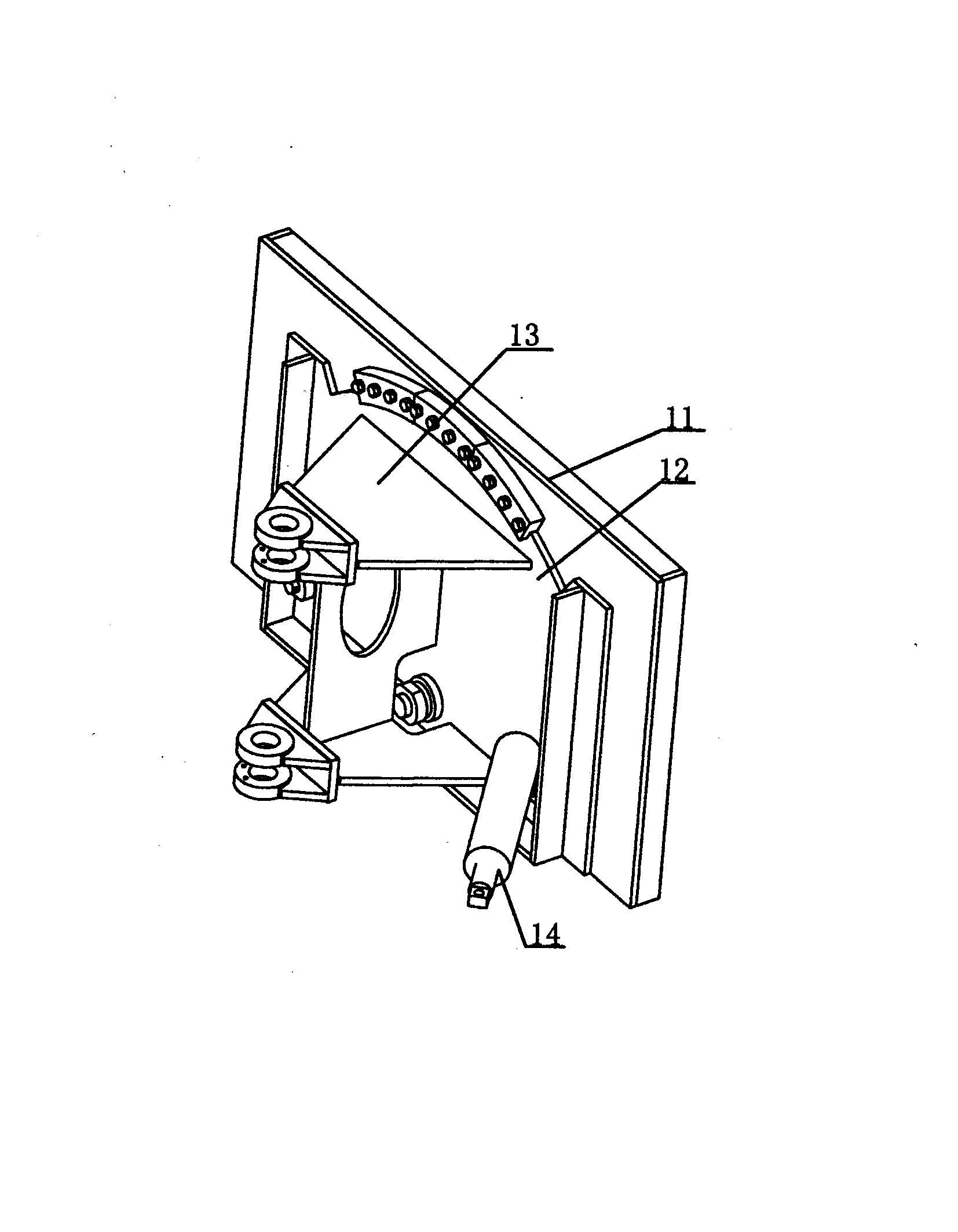
[0033] like Figure 4 As shown, the present invention selects the structure schematic diagram of the ratchet type vibration mechanism; It comprises ratchet 648, ratchet seat 649, ratchet 650, ratchet connecting rod 651 and ratchet connecting rod seat 652, and ratchet 648 wears on the transmission shaft 62 , the pawl seat 649 is fixed on the vibrating arm 61, the pawl 650 is twisted on the pawl seat 649, and meshes with the ratchet 648, the pawl connecting rod seat 652 is fixed on the vibrating beam 63, and the pawl connecting rod 651 One end is twisted on the ratchet connecting rod seat 652, and the other end is connected with the ratchet 650. When the engine or the hydraulic pump drives the transmission shaft 62 to rotate, the transmission shaft 62 drives the ratchet 648 to rotate at the same time, and the pawl 650 drives the pawl connecting rod 651 to generate linear vibration. Under the action of this mechanism, the blade 33 vibrates synchronously.


PUM


Abstract

The invention discloses a shock vibration snow removal device. The shock vibration snow removal device comprises a rear connection plate, a main frame, a snow pushing plate, a shovel blade frame, a shovel blade, a power device, an obstacle crossing device, a vibration device and a power source, wherein the rear connection plate is fixedly installed on a vehicle body, one end of the main frame is hinged to the rear connection plate, the other end of the main frame is fixedly installed on the snow pushing plate, the shovel blade frame is fixedly installed on the lower portion of the vibration device, the shovel blade is fixedly installed on the lower portion of the shovel blade frame, the power device and the power source are fixedly installed on the snow pushing plate, and the obstacle crossing device and the vibration device are hinged to the snow pushing plate. Due to the facts that the independent power device which is provided with an engine and a hydraulic motor is assembled on the shock vibration snow removal device, and the power source is independently installed on the snow pushing plate to drive the power device, the problem that a source of shock vibration power of an existing device is hard to obtain is solved; due to the fact that the obstacle crossing device is arranged, when the shovel blade passes through an obstacle, the shovel blade overcomes pretightening force of springs, overturns backwards to smoothly pass through the obstacle, and immediately resets after passing through the obstacle, and the good snow removal effect is ensured.

Description

technical field [0001] The invention relates to the field of sanitation equipment, in particular to designing an impact vibration snow removal device. Background technique [0002] At present, there are many types of snow removal equipment at home and abroad, but most of them are mainly used to remove primary snow, that is, to clean the ice and snow layer in the form of peeling and scraping, without the function of shock and vibration. For compacted snow and ice, there are many residual ice and snow after cleaning, and the adhesion of these ice and snow to the road surface is very strong. The removal effect of ordinary equipment on ice and compacted snow is not good. It also fails to achieve the desired effect, and when repeated peeling and scraping, a new ice layer is formed on the road surface due to the frictional heat generated between the blade and the ground, resulting in a more slippery road surface, which increases the danger of driving. Most of the snow removal equ...

Claims


Application Information

Patent Timeline
Patent Type & Authority Applications(China)
IPC IPC(8): E01H5/12
Inventor 刘雷
Owner 白山市星泰矿山机械制造有限公司
Why Eureka
Try Eureka