
Display device

A technology for display devices and display modules, applied in rack/frame structure, optics, instruments, etc., can solve problems such as damage to the adhesive layer, increased cost, and long time.

Active Publication Date: 2015-01-21
AU OPTRONICS CORP
View PDF5 Cites 2 Cited by
  • Summary
  • Abstract
  • Description
  • Claims
  • Application Information

AI Technical Summary

Problems solved by technology

However, repairers often need to spend a long time to destroy the glue layer, which will make the rework time too long, thereby increasing the cost

Method used


Image

  • Display device
  • Display device
  • Display device

Examples


Embodiment Construction

[0070] Below in conjunction with accompanying drawing, structural principle and working principle of the present invention are specifically described:

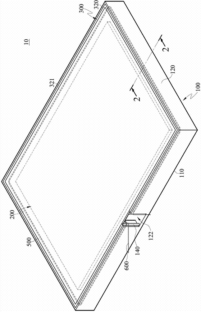
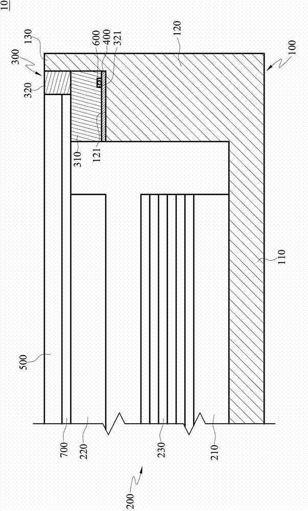
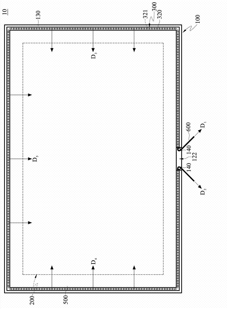
[0071] Please refer to Figure 1 to Figure 3 , figure 1 is a structural diagram of a display device according to an embodiment of the present invention, figure 2 based on figure 1 A sectional view of the 2-2 section line, image 3 is a front view of a display device according to an embodiment of the present invention.

[0072] The display device 10 of this embodiment can be applied to a tablet computer or a liquid crystal screen, but is not limited thereto. The display device 10 includes an outer frame 100 , a display module 200 , a support frame 300 , a first adhesive layer 400 , a transparent plate 500 and a rework line 600 .

[0073] The outer frame 100 includes a base plate 110 and an annular side wall 120 erected on the base plate 110 . The end of the annular side wall 120 away from the base plate 110 has a bearing pl...


PUM


Abstract

The invention discloses a display device comprising an outer frame, a display module, a supporting rack, a first adhesive layer, a light transmitting plate, and a reworking line. The outer frame comprises a bottom plate and an annular-shaped side wall vertically disposed on the bottom plate. One end of the annular-shaped side wall far away from the bottom plate is provided with a carrying platform. The display module is disposed on the bottom plate, and the annular-shaped side wall is disposed along the display module. The supporting rack comprises a frame body, a rib body disposed on the frame body, and a groove disposed in the frame body. The rib body is disposed on the surface opposite to the groove, besides, the elastic coefficient of the material of the rib body is smaller than that of the material of the frame body. The frame body is attached to the carrying platform through the first adhesive layer. The light transmitting plate is overlappedly disposed on the frame body of the supporting frame, and abuts against the rib body, therefore the display module is disposed between the bottom plate and the light transmitting plate. The reworking line is accommodated in the groove.

Description

technical field [0001] The invention relates to a display device, in particular to a display device which is convenient for rework. Background technique [0002] The rapid progress of the multimedia society is mostly benefited from the rapid development of semiconductor devices or display devices. As far as display components are concerned, cathode display tubes (or called image tubes, Cathode Ray Tube, CRT) have been monopolizing the display market due to their excellent display quality and economy. However, CRTs have the problems of being too large and consuming too much energy. For the requirements of high image quality, low power consumption, thin mass production, low voltage drive, and small size, CRT-type displays obviously cannot meet these requirements. In view of this, liquid crystal display (Liquid Crystal Display, referred to as LCD) will have great advantages, and LCD has been widely used in medium and small portable TVs, video phones, camcorders, notebook compu...

Claims


Application Information

Patent Timeline
Patent Type & Authority Patents(China)
IPC IPC(8): G02F1/13H05K7/18
Inventor 郑景鸿黄达人张豫修杨孟融
Owner AU OPTRONICS CORP
Learn More