Terminal apparatus and computer readable medium

A terminal device and data technology, applied in electrical components, wireless communication, transmission systems, etc., can solve the problems of not being used effectively, generating errors in the transfer path, and increasing the update time of the update data, so as to shorten the copy time, reduce the Effect of Operational Burden

Active Publication Date: 2014-01-29
CASIO COMPUTER CO LTD
View PDF5 Cites 3 Cited by
  • Summary
  • Abstract
  • Description
  • Claims
  • Application Information

AI Technical Summary

Problems solved by technology

[0010] In the method of Japanese Unexamined Patent Application Publication No. 2009-89259, the operator's monitoring operation is not required, but the route generation operation of preconsidering and generating the transfer route of the update data is required.
In order to efficiently perform data transfer and update, it is preferable to consider the transfer route, and the burden of route creation operation is large, and there is a possibility that a transfer route generation error may occur
[0011] In addition, in the method of the above-mentioned Patent Document 1, the transfer path is serially connected or tree-shaped, and the transfer source terminal device that has completed the data transfer to the subordinate transfer destination terminal device does not perform update data transfer, so there is no are effectively used, so the update time of update data may increase

Method used


Image

  • Terminal apparatus and computer readable medium
  • Terminal apparatus and computer readable medium
  • Terminal apparatus and computer readable medium

Examples


no. 1 approach

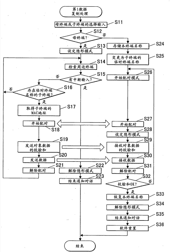
[0031] First, refer to figure 1 and figure 2 , to describe the device structure of this embodiment.

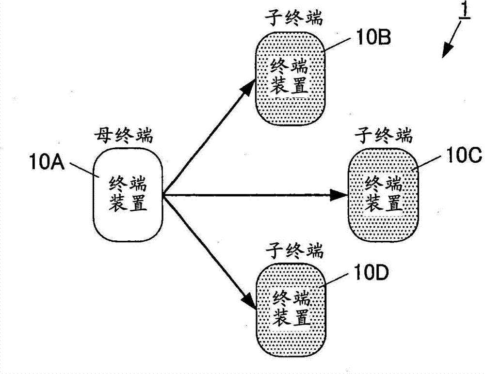
[0032] figure 1 It is a block diagram showing the terminal management system 1 of this embodiment.

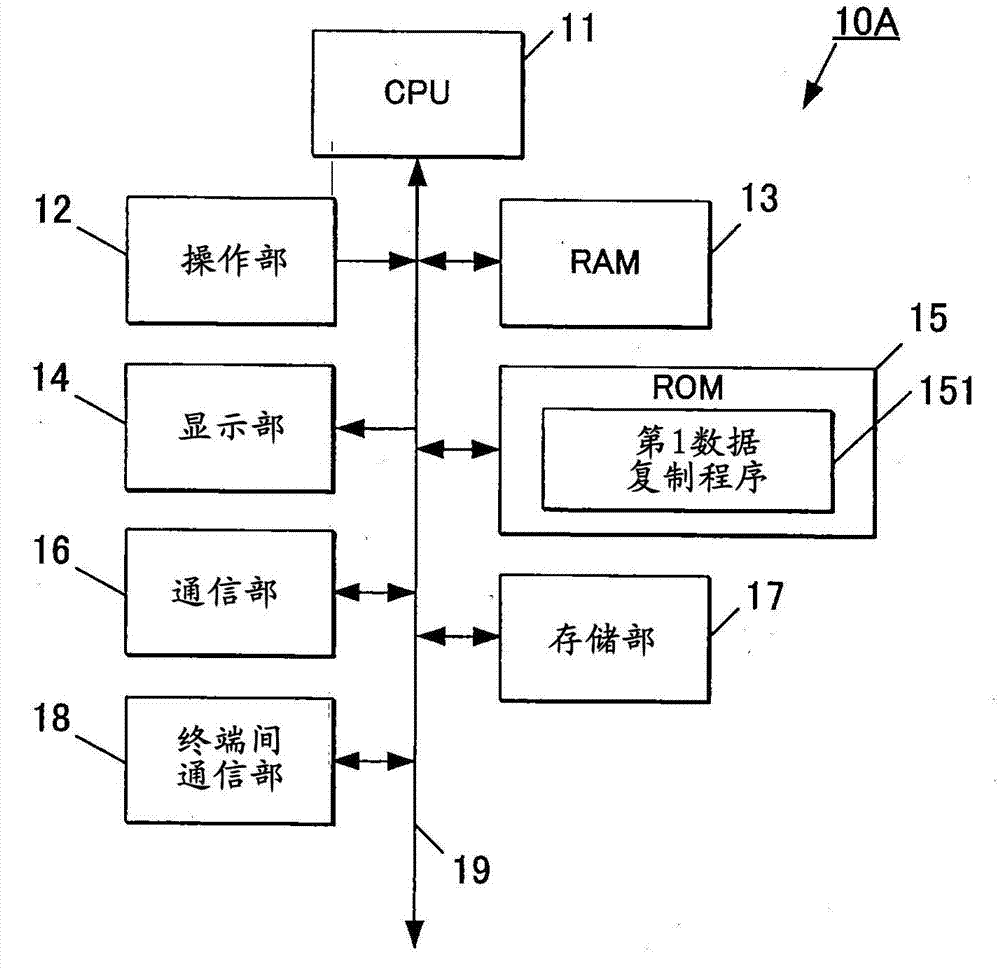
[0033] figure 2 It is a block diagram showing the functional configuration of the terminal device 10A.

[0034] The terminal management system 1 is a system for a supplier of terminal devices or a user who owns a plurality of terminal devices, and is a system for duplicating and storing the same data in all terminal devices included in the terminal management system 1 .

[0035] The deliverer delivers to the customer a plurality of terminal devices generated by the terminal management system 1 and storing the same data. A user (for example, a carrier) who owns a plurality of terminal devices makes a plurality of employees use the plurality of terminal devices generated by the terminal management system 1 and storing the same data.

[0036] Such as figure 1 As shown, th...

no. 2 approach )

[0118] refer to Figure 5 to Figure 7B , to describe the second embodiment of the present invention.

[0119] First, refer to Figure 5 , to describe the device structure of this embodiment. Figure 5 It is a block diagram showing the terminal management system 2 of this embodiment.

[0120] In this embodiment, at least one group is set in the terminal management system, and a terminal device that is a replica of a parent terminal different from each other in each group is generated. The terminal device of the parent terminal and the terminal device of the child terminal belong to each group.

[0121] Such as Figure 5 As shown, the terminal management system 2 includes terminal devices 10E, 10F, 10G, 10H, 10I, 10J, and 10K.

[0122] In the terminal management system 2, as an example, two groups g1 and g2 are set.

[0123] The terminal devices 10E, 10G, 10J, and 10K belong to the group g1. The terminal device 10E is a parent terminal of the group g1, and the terminal de...

no. 3 approach )

[0176] refer to Figure 8 to Figure 10B , to describe the third embodiment of the present invention.

[0177] First, refer to Figure 8 , to describe the device structure of this embodiment.

[0178] Figure 8 It is a block diagram showing the terminal management system 3 of this embodiment.

[0179] In this embodiment, at least one group is set in the terminal management system, terminal devices that are replicas of the parent terminal different from each other are generated in each group, and the copied child terminal is restored to the parent terminal. In addition, in this embodiment, "reverting to the parent terminal" means that the copied child terminal is set as the parent terminal, and will operate as the parent terminal thereafter.

[0180] Such as Figure 8 As shown, the terminal management system 3 includes terminal devices 10-0 to 10-48.

[0181] In the terminal management system 3, one group g1 is set as an example. That is, the terminal devices 10-0 to 10-4...


PUM


Abstract

Disclosed is a terminal apparatus including a communication unit which performs a wireless communication with another terminal apparatus and a determination unit which determines whether a terminal apparatus which is a sub terminal into, which data subject to copying is to be copied, exists through the communication via the communication unit, the terminal apparatus which is the sub terminal being a terminal apparatus to which the data is not yet transmitted, if the terminal apparatus is a main terminal from which the data is copied. Further including a control unit which reads out the data from a storage unit and transmits the data to the terminal apparatus which is the sub terminal determined to exist via the communication unit if the determination unit determines that the terminal apparatus which is the sub terminal exists.

Description

technical field [0001] The present invention relates to a terminal device and a data transmission method. Background technique [0002] Conventionally, a delivery provider of terminal devices such as portable terminals may deliver a plurality of identical terminal devices to customers. The number of such terminal devices sometimes reaches several hundreds. In this case, terminal devices are set one by one through the following procedures (1) to (4) performed by the operator. In addition, the terminal device on the sending side of data is used as a parent terminal, and the terminal device on the receiving side of data is used as a child terminal. [0003] (1) Make one terminal device that is a parent terminal operable. Specifically, application installation and various settings are performed on the parent terminal. [0004] (2) Generate a backup image file as data of the parent terminal. [0005] (3) Copy the backup image file of the parent terminal to the sub-terminal. ...

Claims


Application Information

Patent Timeline
Patent Type & Authority Applications(China)
IPC IPC(8): H04L29/08
CPCH04L67/42H04L67/125H04W24/00H04W88/02H04L41/0806H04L41/0846H04L67/01
Inventor 大隅刚志谷冈惠一
Owner CASIO COMPUTER CO LTD
Why Eureka
Try Eureka