Data transform apparatus and control method thereof
a data transform and control method technology, applied in the field of data transform technique, can solve problems such as unsuitable for fast transform processing, and achieve the effect of improving such points
- Summary
- Abstract
- Description
- Claims
- Application Information
AI Technical Summary
Benefits of technology
Problems solved by technology
Method used
Image
Examples
first embodiment
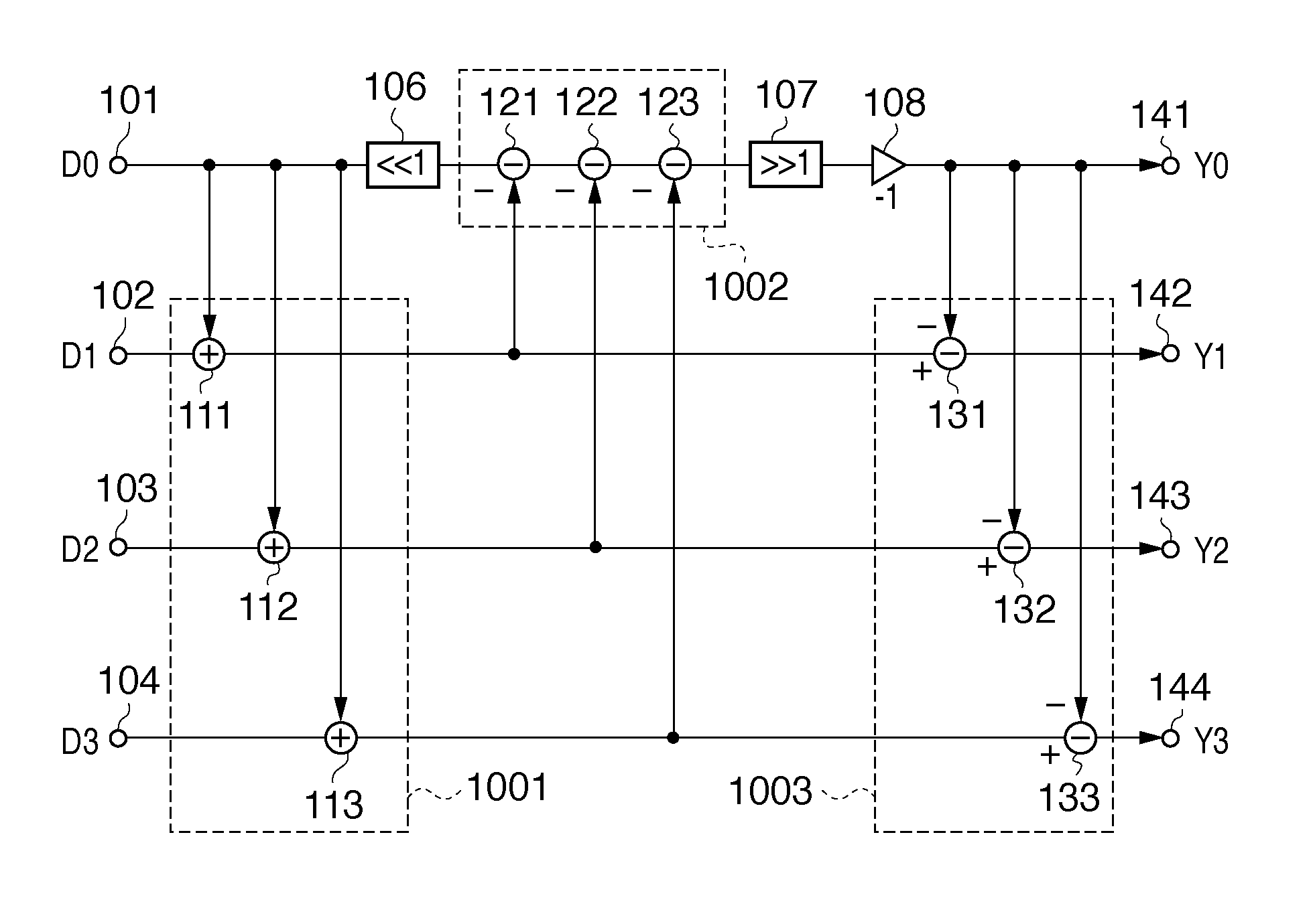
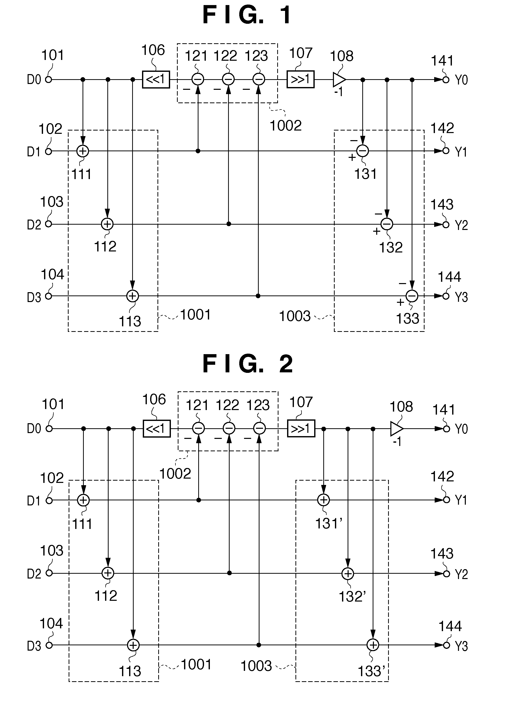
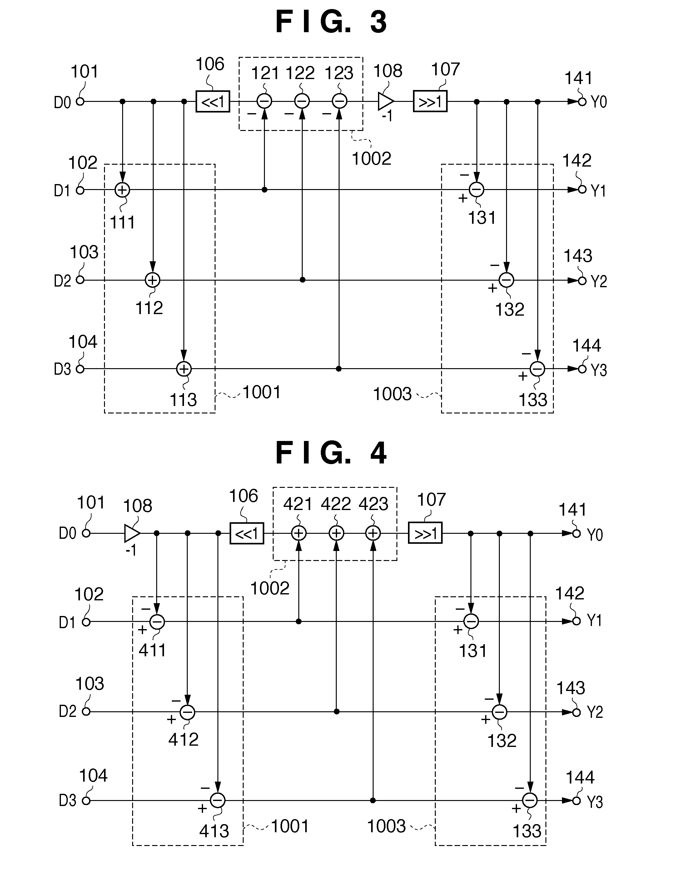
[0055]FIG. 1 shows the circuit arrangement of a data transform apparatus (lossless 4-point Hadamard transform apparatus) according to the present invention, and the control processing contents of this apparatus will be described below.
[0056]Referring to FIG. 1, reference numerals 101 to 104 denote terminals (first to fourth input terminals) for inputting four, integer-represented data D0, D1, D2, and D3 (transforms target data).
[0057]Reference numerals 111 to 113 denote adders. These three adders form a first calculation unit group 1001. Reference numerals 121 to 123 denote subtractors. These three subtractors form a second calculation unit group 1002. Reference numerals 131 to 133 denote subtractors. These three subtractors form a third calculation unit group 1003. Reference numeral 141 to 144 denote output terminals (first to fourth output terminals) for outputting lossless-Hadamard transform results as Y0 to Y3. Y0 represents a DC coefficient obtained by the Hadamard transform, a...
second embodiment
[0110]FIG. 11 shows the arrangement according to the present invention. Referring to FIG. 11, reference numerals 811 to 813 denote three subtractors which form a first calculation unit group 1001; 821 to 823, three adders which form a second calculation unit group 1002; and 831 to 833, three subtractors which form a third calculation unit group 1003. In FIG. 1, the first and third calculation unit groups 1001 and 1003 are arranged on the second to fourth paths, and the second calculation unit group 1002 is arranged on the first path. It should be noted that in FIG. 11, this layout relationship is reversed, i.e., the first and third calculation unit groups 1001 and 1003 are arranged on the first path, and the second calculation unit group 1002 is arranged on the second to fourth paths.
[0111]Reference numeral 841 denotes an adder which adds a least significant bit (LSB) of the calculation result by the first calculation unit group 1001.
[0112]As for other components, the same reference...
third embodiment
[0142]FIG. 15 shows the arrangement according to the present invention.
[0143]In the first and second embodiments and their modifications described so far, a focus of the calculations is the DC coefficient.
[0144]More specifically, data to be commonly added or subtracted is output as DC coefficient data Y0 from the output terminal 141 by applying various calculations to data D0 input from the input terminal 101 in the first to third calculation unit groups.
[0145]In this embodiment, data to be commonly added to or subtracted from is data on a path which applies calculations to data input from the terminal 102 and outputs that data as an AC coefficient from the output terminal 142. This is the largest feature of the third embodiment.
[0146]Referring to FIG. 15, reference numerals 941 to 943 respectively denote one adder and two subtractors, which form a first calculation unit group 1001. Reference numeral 951 to 953 respectively denote one subtractor and two adders which are arranged on ...
PUM
 Abstract
Description
Claims
Application Information
 - R&D
- Intellectual Property
- Life Sciences
- Materials
- Tech Scout
- Unparalleled Data Quality
- Higher Quality Content
- 60% Fewer Hallucinations
Browse by: Latest US Patents, China's latest patents, Technical Efficacy Thesaurus, Application Domain, Technology Topic, Popular Technical Reports.
© 2025 PatSnap. All rights reserved.Legal|Privacy policy|Modern Slavery Act Transparency Statement|Sitemap|About US| Contact US: help@patsnap.com


