
Eureka
For R&D, Eureka makes reading and utilizing patents & technical documents easy.
Eureka AIR
Designed for self-driven R&D workflows. Generate viable solutions, solve complex R&D challenges, empower your innovation with AI.

Eureka Materials
Designed for material experts only. Revolutionize your material R&D, from search, analyze, to developing new materials.

TechResearch
Generate reliable direction feasibility study reports for your R&D in just a few steps.

TechSeek
Discover and master advanced knowledge NOW. Basics, ideas, possibilities, all at once.

TechMind
As an expert in R&D Theories, TechMind can generates customized viable solutions instantly.

TechRisk
Analyze your overall solution with one click, know your potential R&D risks in advance.

TechMonitor
Get weekly tech updates, stay abreast of the latest tech innovations and key insights.
Measuring device for the low-frequency oscillation of the discharge current of the Hall electric thruster in the state of orbital operation
A technology of electric thruster and operating state, which is applied to measurement devices, measurement of electrical variables, measurement of current/voltage, etc., can solve problems such as the inability to easily obtain low-frequency oscillating waveforms
- Summary
- Abstract
- Description
- Claims
- Application Information
AI Technical Summary
Problems solved by technology
Method used
Image

Examples
specific Embodiment approach 1
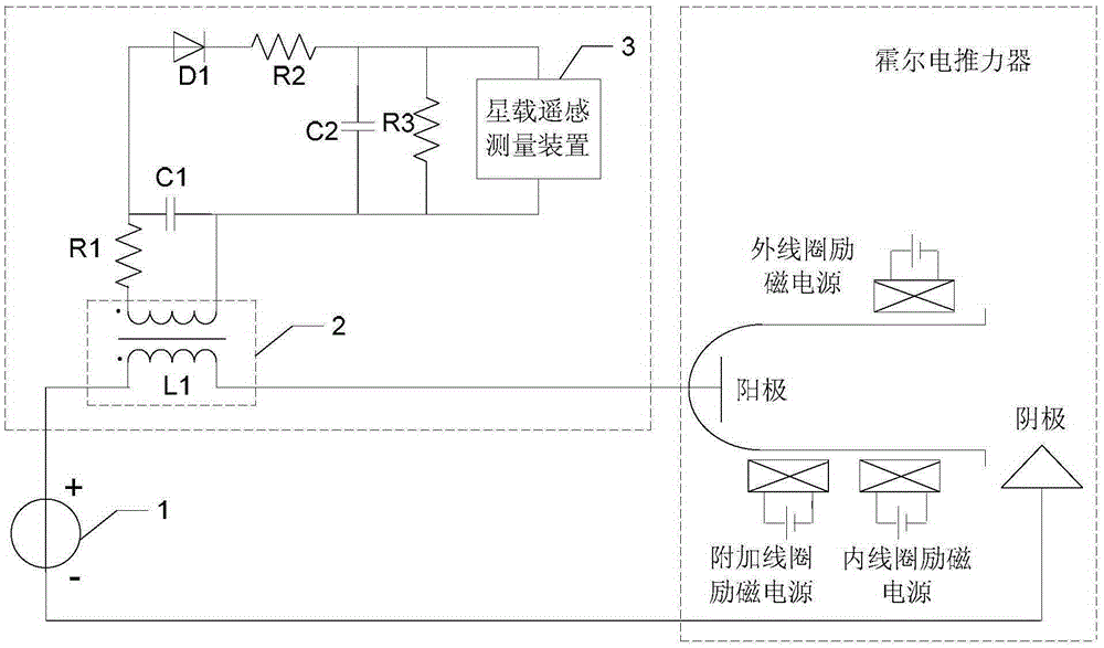
[0014] Specific implementation mode one: the following combination figure 1 Describe this embodiment, the measurement device for the low-frequency oscillation of the discharge current of the Hall electric thruster in the on-rail operating state described in this embodiment, the Hall electric thruster includes a DC power supply 1, and the Hall electric thruster in the on-rail operating state The measuring device for low-frequency oscillation of the thruster discharge current includes a transformer 2, a high-frequency filter resistor R1, a high-frequency filter capacitor C1, a rectifier diode D1, a current limiting resistor R2, a filter capacitor C2, a discharge resistor R3 and an on-board remote sensing measurement device 3;
[0015] The negative pole of the DC power supply 1 is connected to the cathode of the Hall electric thruster;
[0016] The positive pole of the DC power supply 1 is connected to the same-named end of the primary coil L1 of the transformer 2, and the differ...
specific Embodiment approach 2
[0026] Specific Embodiment 2: The working principle will be described below in conjunction with a specific embodiment.
[0027] An additional coil is wound on the inductance L1=0.1mH to form a transformer 2; the discharge current oscillation amplitude is sampled by means of electromagnetic induction, and the turns ratio n of the primary and secondary coils is 1:1.4. Then connect high-frequency filter resistor R1=100Ω and high-frequency filter capacitor C1=33nF in parallel to filter the high-frequency signal to obtain a low-frequency oscillation signal. The -3dB frequency potential of the filter circuit composed of R1 and C1 is 48KHz. After sampling the low-frequency oscillation signal, the rectifier diode D1 is connected in series in the circuit for rectification. The rectifier diode D1 has a forward voltage drop, so if it works in the nonlinear region, it will bring a nonlinear quantity to the signal and affect the measurement results, so this part uses the detection characte...
PUM
 Abstract
Description
Claims
Application Information
 - R&D Engineer
- R&D Manager
- IP Professional
- Industry Leading Data Capabilities
- Powerful AI technology
- Patent DNA Extraction
Browse by: Latest US Patents, China's latest patents, Technical Efficacy Thesaurus, Application Domain, Technology Topic, Popular Technical Reports.
© 2024 PatSnap. All rights reserved.Legal|Privacy policy|Modern Slavery Act Transparency Statement|Sitemap|About US| Contact US: help@patsnap.com