
Bidirectional and synchronous riveting method of U-type section part

A two-way synchronous, parts technology, applied in the field of two-way synchronous riveting of U-shaped section parts, to achieve the effect of solving low efficiency

Inactive Publication Date: 2014-02-19
SHIYAN HANTANG ELECTROMECHANICAL ENG
View PDF6 Cites 1 Cited by
  • Summary
  • Abstract
  • Description
  • Claims
  • Application Information

AI Technical Summary

Problems solved by technology

[0003] In order to overcome the problem that the existing unidirectional action riveting can not enter the riveting of smaller or narrow U-shaped cross-section parts, realize the bidirectional synchronous riveting of U-shaped cross-section parts, and improve the riveting efficiency, the present invention proposes two-way synchronous riveting of U-shaped cross-section parts method

Method used


Image

  • Bidirectional and synchronous riveting method of U-type section part
  • Bidirectional and synchronous riveting method of U-type section part
  • Bidirectional and synchronous riveting method of U-type section part

Examples


Embodiment Construction

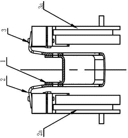
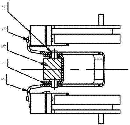
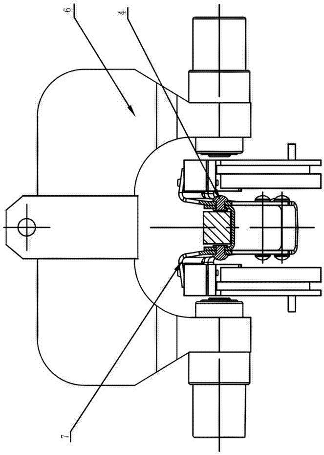
[0014] combine figure 1 , figure 2 , image 3 As shown, the present invention is further described as follows: a method for bidirectional synchronous riveting of U-shaped cross-section parts, the parts involved are a U-shaped cross-section part 1, a left workpiece 2 to be riveted, and a right workpiece 3 to be riveted. The specific steps are:

[0015] (1). Parts positioning: After positioning the U-shaped section part 1, then fit the left workpiece 2 to be riveted and the right workpiece 3 to be riveted to ensure that the left workpiece to be riveted and the U-shaped section part and the right workpiece to be riveted and the U Accurate positioning between cross-section parts; such as figure 1 As shown, the positioning between the left workpiece 2 to be riveted and the U-shaped section part is ensured by the left workpiece positioning bracket 2a, and the positioning between the right workpiece 3 to be riveted and the U-shaped section part is guaranteed by the right workpiece...


PUM


Abstract

The invention provides a bidirectional and synchronous riveting method of a U-type section part. The method comprises the specific steps that (1), accurate positioning is carried out between a left workpiece to be riveted and the U-type section part and between a right workpiece to be riveted and the U-type section part; (2), rivets are manually installed outwards from an inner cavity of the U-type section part; (3), a middle pneumatic compression resistance cushion block extends into the inner cavity of the U-type section part, the two side faces of the middle pneumatic compression resistance cushion block just make contact with the outer ends of the head portions of the rivets on the two sides; (4), synchronous riveting is carried out on the two rivets corresponding to each riveting position in sequence through a bidirectional hydraulic synchronous rivet clamp, the middle pneumatic compression resistance cushion block bears the symmetrical riveting force at the same time to achieve the bidirectional and synchronous riveting, the middle pneumatic compression resistance cushion block is retracted, positioning is released, and then the bidirectional and synchronous riveting of the U-type section part is finished. According to the bidirectional and synchronous riveting method of the U-type section part, the bidirectional hydraulic synchronous rivet clamp is combined with the middle pneumatic compression resistance cushion block, the bidirectional riveting function of the U-type section part is achieved ingeniously, and the efficiency is high.

Description

technical field [0001] The invention relates to a two-way synchronous riveting method for U-shaped cross-section parts, and is especially suitable for occasions where small or narrow U-shaped cross-section parts cannot be riveted by traditional one-way riveting technology. Background technique [0002] At present, the riveting process of domestic auto parts adopts the traditional one-way riveting method, such as horizontal one-way riveting pliers, vertical one-way riveting pliers; when small or narrow U-shaped cross-section parts need to be riveted, Since the external dimension of the static riveting seat of the traditional one-way riveting pliers is much larger than the U-shaped cross-section size of the part, it cannot enter the cavity of the U-shaped cross-section part for riveting. Therefore, the traditional one-way riveting method is not only applicable to There are greater limitations, and its riveting efficiency is also low. Contents of the invention [0003] In or...

Claims


Application Information

Patent Timeline
Patent Type & Authority Applications(China)
IPC IPC(8): B21J15/14
Inventor 段刚毕亚球
Owner SHIYAN HANTANG ELECTROMECHANICAL ENG
Learn More