Bidirectional and synchronous riveting equipment of U-type section part

A two-way synchronization, parts technology, applied in the field of two-way synchronous riveting equipment, achieves the effect of good safety and reliability, improved riveting function and efficiency, and solved inefficiency

Inactive Publication Date: 2014-02-19
SHIYAN HANTANG ELECTROMECHANICAL ENG
View PDF6 Cites 4 Cited by
  • Summary
  • Abstract
  • Description
  • Claims
  • Application Information

AI Technical Summary

Problems solved by technology

[0003] In order to overcome the problem that the existing unidirectional riveting pliers cannot enter the small or narrow U-shaped cross-section parts for riveting, realize the bidirectional synchronous riveting of U-shaped cross-section parts, and improve the riveting efficiency, the present invention proposes two-way synchronous Riveting equipment, through hydraulic power bidirectional synchronous riveting pliers, pneumatic anti-pressure pad telescopic mechanism, pneumatic parts assembly and pushing mechanism, parts in-place detection mechanism, pneumatic telescopic positioning protection mechanism and electrical control system, etc., to realize U-shaped riveting fixture. Riveting function for cross-sectional parts

Method used


Image

  • Bidirectional and synchronous riveting equipment of U-type section part
  • Bidirectional and synchronous riveting equipment of U-type section part
  • Bidirectional and synchronous riveting equipment of U-type section part

Examples


Embodiment Construction

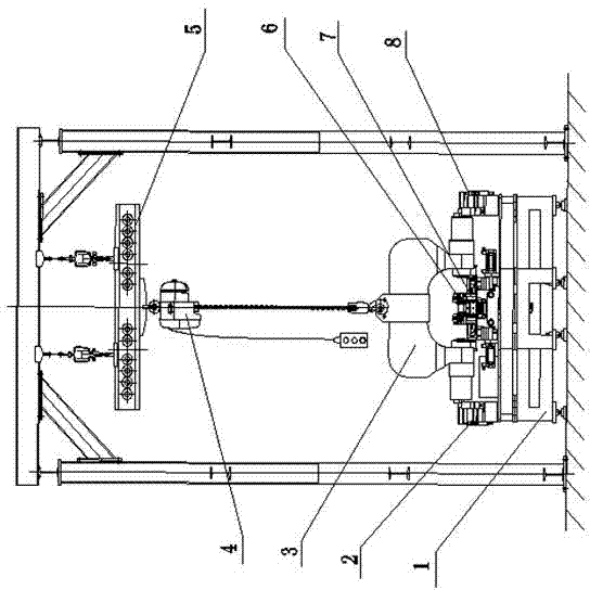
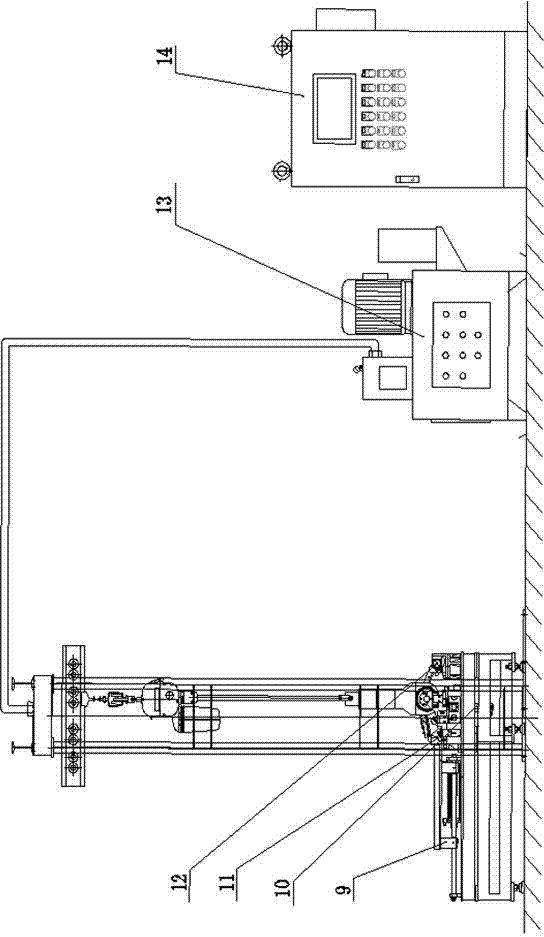
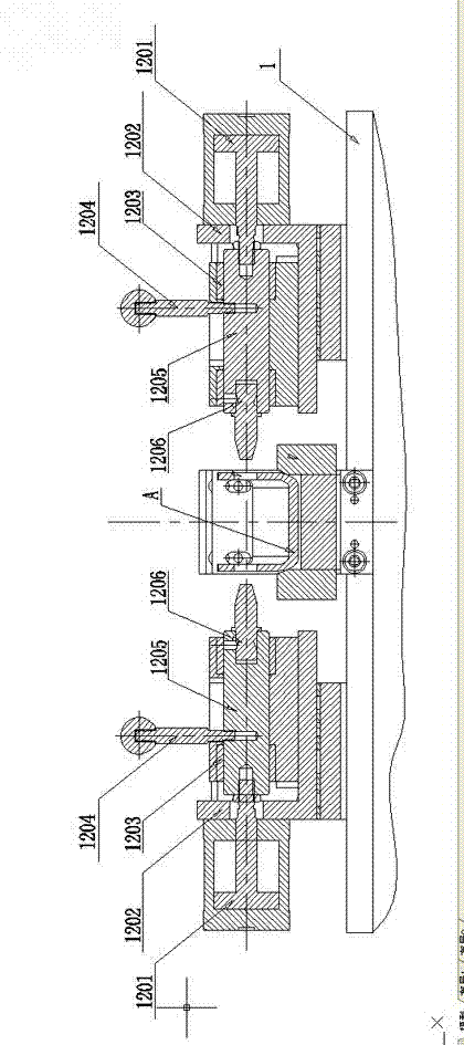
[0022] Such as figure 1 , figure 2 The two-way synchronous riveting equipment for U-section parts shown includes riveting fixture frame 1, riveting pliers left positioning base 2, riveting pliers right positioning base 8, bidirectional hydraulic synchronous riveting pliers 3, electric chain hoist 4, KPK suspension Steel frame 5, parts in place detection mechanism 6, pneumatic parts assembly push mechanism 7, pneumatic anti-pressure pad telescopic mechanism 9, pneumatic telescopic positioning and protection mechanism 10, pneumatic telescopic pin positioning mechanism 12, hydraulic power station 13, electrical control system 14. The pneumatic telescopic pin positioning mechanism 12 is arranged on the near end of the riveting fixture frame 1 along the length direction, and the middle of the riveting fixture frame along the length direction is a U-shaped cross-section part support pad 11, and the U-shaped cross-section part support pad Positioning pins are arranged on 11; U-shap...


PUM


Abstract

The invention provides bidirectional and synchronous riveting equipment of a U-type section part. The bidirectional and synchronous riveting equipment of the U-type section part comprises a riveting clamp machine frame, a riveting clamp left locating base, a riveting clamp right locating base, a bidirectional hydraulic synchronous riveting clamp, an electric chain hoist, a KPK hanging steel frame, a part in-place detection mechanism, a pneumatic part combined loading pushing mechanism, a pneumatic compression resistance cushion block telescopic mechanism, a pneumatic telescopic locating protective mechanism, a pneumatic telescopic pin locating mechanism, a hydraulic power station and an electrical control system, wherein the hydraulic power station is a power source, and the electrical control system is a control part. The bidirectional and synchronous riveting equipment of the U-type section part is characterized in that the inner ends of rivets are located through the pneumatic compression resistance cushion block telescopic mechanism. According to the acting force and counter-acting force law, the bidirectional hydraulic synchronous riveting clamp is combined with a compression resistance cushion block in the middle of a U-type section cavity, the bidirectional riveting function of the U-type section part is achieved ingeniously, and the problem that the efficiency of a one-way riveting process of various U-type section parts is low is solved.

Description

technical field [0001] The invention relates to two-way synchronous riveting equipment for U-shaped cross-section parts, and is especially suitable for occasions where small or narrow U-shaped cross-section parts cannot be riveted by traditional one-way riveting technology. Background technique [0002] At present, the riveting process device of domestic auto parts adopts traditional one-way action riveting pliers, such as horizontal one-way action riveting pliers, vertical one-way action riveting pliers. In terms of riveting process devices for larger U-shaped cross-section parts, this traditional one-way riveting pliers is also used, such as frame longitudinal beams, beams and other workpieces; when small or narrow U-shaped cross-section parts need to be riveted, Since the external dimension of the static riveting seat of the traditional one-way riveting pliers is much larger than the U-shaped section size of the part, it cannot enter the cavity of the U-shaped section par...

Claims


Application Information

Patent Timeline
Patent Type & Authority Applications(China)
IPC IPC(8): B21J15/14B21J15/20B21J15/38
Inventor 段刚毕亚球张军
Owner SHIYAN HANTANG ELECTROMECHANICAL ENG
Why Eureka
Try Eureka