Antenna fault detection method and device

A technology for detecting device and fault location, which is applied in the field of communication and can solve problems such as antenna faults

Active Publication Date: 2014-02-19
HUAWEI TECH CO LTD
View PDF3 Cites 11 Cited by
  • Summary
  • Abstract
  • Description
  • Claims
  • Application Information

AI Technical Summary

Problems solved by technology

[0006] The purpose of the present invention is to solve the problem in the prior art that the antenna failure information is obtained after the user generates a radio frequency signal when making a call, and provides a method and device for detecting antenna failure

Method used


Image

  • Antenna fault detection method and device
  • Antenna fault detection method and device
  • Antenna fault detection method and device

Examples


Embodiment Construction

[0029] In order to make the object, technical solution and advantages of the present invention clearer, the specific embodiments of the present invention will be further described in detail below in conjunction with the accompanying drawings.

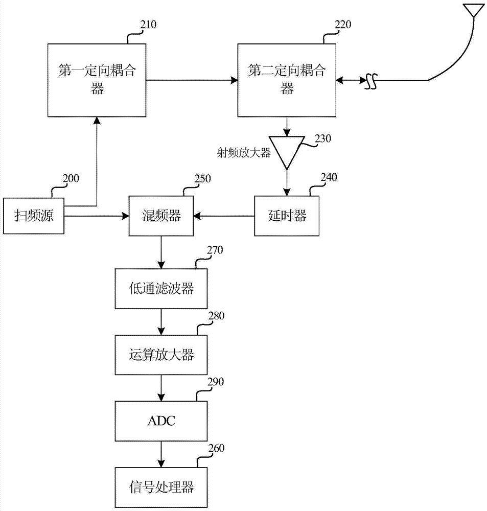
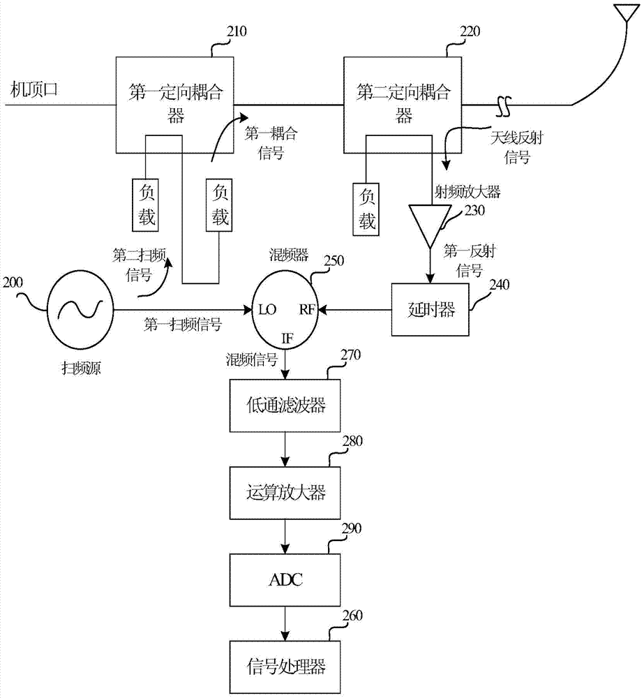
[0030] Below to figure 2 example and combine image 3 Describe in detail the antenna fault detection device provided by the embodiment of the present invention, figure 2 Diagram of the detection device for antenna failure provided by the embodiment of the present invention; image 3 The flow chart of the antenna fault detection signal provided by the embodiment of the present invention.

[0031] Such as figure 2 As shown, the antenna fault detection device includes: frequency sweep source 200, first directional coupler 210, second directional coupler 220, radio frequency amplifier 230, delayer 240, mixer 250 and signal processing device 260.

[0032] The frequency sweeping source 210 is used to generate a first frequency sweepin...


PUM


Abstract

Embodiments of the present invention relate to an antenna fault detection method and apparatus. The apparatus comprises: a sweep source, used for generating a first sweep signal and a second sweep signal; a first directional coupler, used for generating a first coupling signal from the second sweep signal; a second directional coupler, used for performing coupling processing on the first coupling signal, generating a second coupling signal, transmitting the second coupling signal through an antenna, performing coupling processing on an antenna reflection signal used for the antenna to receive the second coupling signal, and generating an antenna coupling reflection signal; a radio frequency amplifier, used for generating a first reflection signal after amplifying the antenna coupling reflection signal; a delayer, used for delaying the first reflection signal, and generating the first delayed reflection signal; a mixer, used for mixing the first sweep signal and the first delayed reflection signal to generate a mixed signal; and a signal processor, used for processing the mixed signal generated by the mixer, and obtaining fault information of the antenna.

Description

technical field [0001] The invention relates to the technical field of communications, in particular to a method and device for detecting antenna faults. Background technique [0002] With the rapid development of mobile communication, active antenna system (Active Antenna System, AAS) is increasingly widely used in communication, satellite navigation and aerospace measurement and control and other fields. [0003] The active antenna system uses radio frequency multi-channel technology to control the vertical and horizontal sub-arrays of the antenna, and flexibly controls the vertical and horizontal beams of the antenna, thereby improving the coverage quality of wireless signals and improving network capacity. the goal of. [0004] At present, in existing solutions for detecting active antenna faults, a standing wave detection circuit is added to detect antenna faults. The standing wave detection method adopts the method of detecting the power of the transmitted radio freq...

Claims


Application Information

Patent Timeline
Patent Type & Authority Applications(China)
IPC IPC(8): A99Z99/00
CPCH04B17/17
Inventor 岳建军
Owner HUAWEI TECH CO LTD
Why Eureka
Try Eureka