
Home electric appliance

A kind of home appliance equipment and hope technology, applied in the direction of electrical components, circuit devices, AC network circuits, etc., can solve the problems of high electricity price, wrinkled clothes, dissatisfaction with the completion results, etc.

Inactive Publication Date: 2014-03-12
PANASONIC CORP
View PDF8 Cites 2 Cited by
  • Summary
  • Abstract
  • Description
  • Claims
  • Application Information

AI Technical Summary

Problems solved by technology

For example, in the case of operating a home appliance during a time when electricity is cheap, the user feels dissatisfied that the home appliance is not operated at the desired time, and the clothes are easily wrinkled because the clothes are dried earlier than the appropriate time. High dissatisfaction with the results
Conversely, there are cases where the electricity price is higher than normal because the home appliances are prioritized to be operated at the user's desired time, and clothes are dried at a time when clothes are not easily wrinkled.

Method used


Image

  • Home electric appliance
  • Home electric appliance
  • Home electric appliance

Examples


Embodiment approach 1

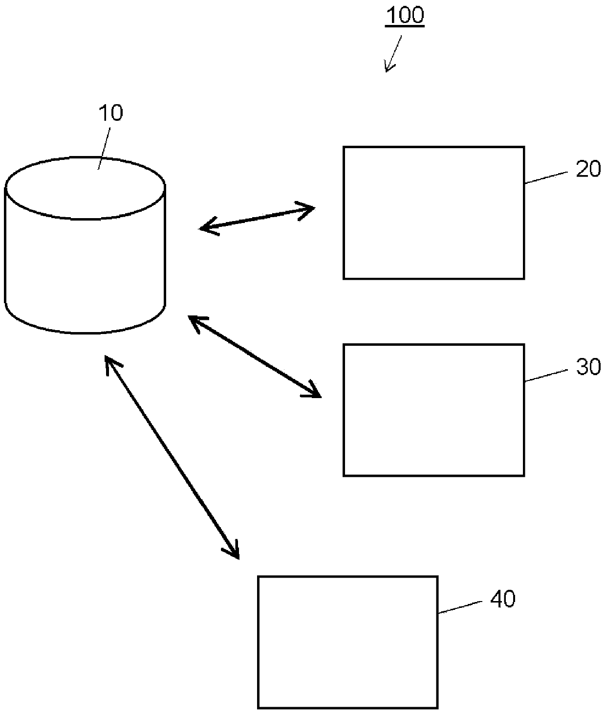
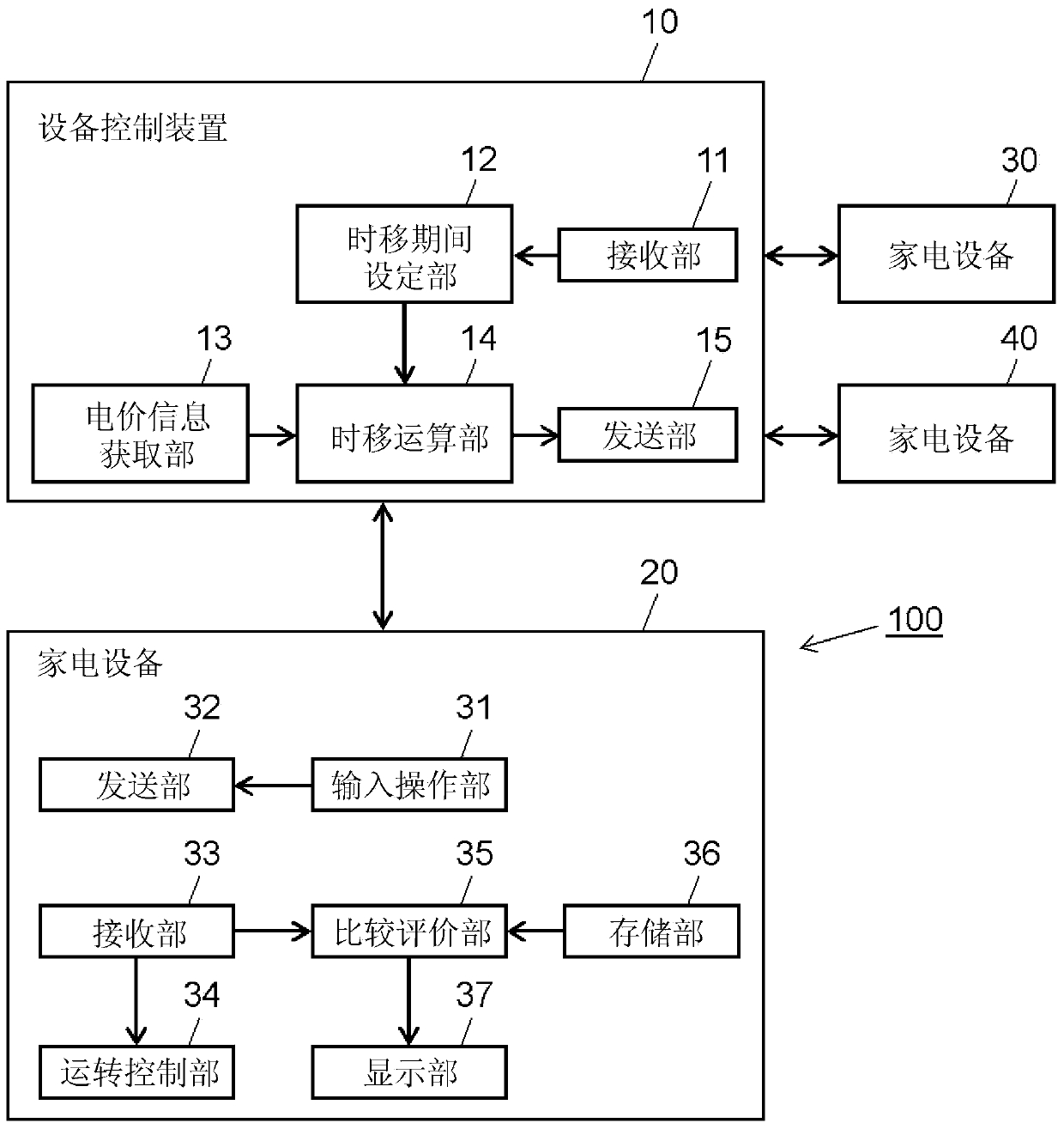
[0037] figure 1 It is an explanatory diagram showing a schematic configuration of the device control system according to Embodiment 1 of the present invention. figure 1 The illustrated appliance control system 100 includes an appliance control device 10 and home appliances 20 , 30 , and 40 .

[0038] In the present embodiment, a washing and drying machine will be described as an example of a household electrical appliance, but the household electrical appliance of the present invention is not limited thereto, and it can be suitably applied to a household electrical appliance having a timer scheduled operation function for both operation start and operation end. . Examples of such home appliances include air conditioners, washing machines, clothes dryers, electromagnetic conditioners (IH), electric water heaters, dishwashers, rice cookers, and garbage disposals.

[0039] The appliance control device 10 and the home appliances 20 , 30 , and 40 are connected so as to be able to...


PUM


Abstract

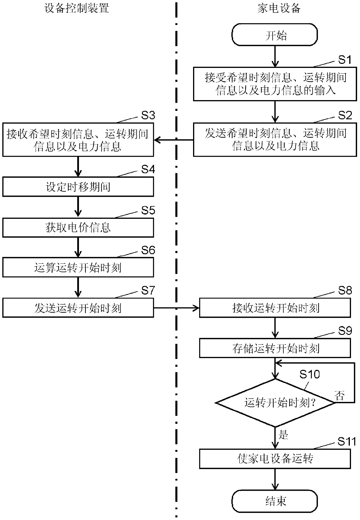
A home electric appliance of the present invention comprises: an input operation unit for inputting desired time information indicating desired operation start time or desired operation end time; a receiving unit for receiving a time shift calculation result including operation start time or operation end time that makes an electricity rate less than or equal to a predetermined rate, the electricity rate being charged when the home electric appliance is operated within a period determined by the desired time information, and also including the electricity rate charged at the operation start time or the operation end time; a storage unit for storing a reference value used for evaluating the time shift calculation result; a comparison evaluating unit for performing comparison processing for comparing the time shift calculation result with the reference value stored in the storage unit; an operation control unit for controlling the operation on the basis of the time shift calculation result; and a display unit for displaying the information about the operation. The display unit changes a display mode according to the comparison result by the comparison evaluating unit.

Description

technical field [0001] The present invention relates to a household electrical appliance that controls an operation start time or an operation end time. Background technique [0002] Conventionally, there has been proposed a power load leveling system that prompts each consumer to use electric power during the time period of the day when the load on the power supply device of the power company is low (for example, refer to Patent Document 1). [0003] In the power load leveling system described above, by presenting to each consumer a time period (recommended power usage time) of a day when the load of the power supply device is low, the use of electric power during the time period is promoted, and the low-peak power of power demand can be increased. . In addition, at the same time, it is also desirable to reduce the peak power of the power demand and to average the load of the power supply device as a whole. [0004] In addition, by leveling the load of the power supply de...

Claims


Application Information

Patent Timeline
Patent Type & Authority Applications(China)
IPC IPC(8): H02J3/00
CPCG05B15/02G04G15/006Y02B70/3225Y04S20/222Y04S20/242Y04S40/126H02J2310/64H02J2310/14H02J13/00004H02J3/14Y02B70/30Y02B90/20Y02P80/10Y04S50/10Y04S20/00H02J13/00001H02J13/00006Y04S40/12
Inventor 甲田哲也池田俊久吉村康男高山久胁有纪
Owner PANASONIC CORP
Learn More