
Home electric appliance

a technology for home electric appliances and time-shift functions, which is applied in the direction of process and machine control, computer control, instruments, etc., can solve the problems of insufficient investigation on how to use the time-shift function of the home electric appliance, laundry clothes tend to crease, and the inability to operate in the desired time. , to achieve the effect of low electricity rate and simple and intuitive operation setting

Inactive Publication Date: 2014-03-27
PANASONIC INTELLECTUAL PROPERTY MANAGEMENT CO LTD
View PDF9 Cites 4 Cited by
  • Summary
  • Abstract
  • Description
  • Claims
  • Application Information

AI Technical Summary

Benefits of technology

The patent describes a configuration that makes it easy to operate a home appliance and reduces the amount of electricity used. The technical effect of this configuration is user satisfaction and cost savings.

Problems solved by technology

However, in the above-mentioned conventional technologies, there is description of an algorithm for shifting working time of the home electric appliance to the optimum time zone in consideration of the electricity rate, or the like, but sufficient investigation has not been made on how to use a time-shift function of the home electric appliance.
For example, when a user operates a home electric appliance in the time zone in which an electricity rate is low, the user tends to have dissatisfaction that the home electric appliance cannot be operated in desired time, and has higher dissatisfaction with finishing results that laundry clothes tend to have creases because drying of laundry clothes is carried out earlier than an appropriate time zone.

Method used


Image

  • Home electric appliance
  • Home electric appliance
  • Home electric appliance

Examples


first exemplary embodiment

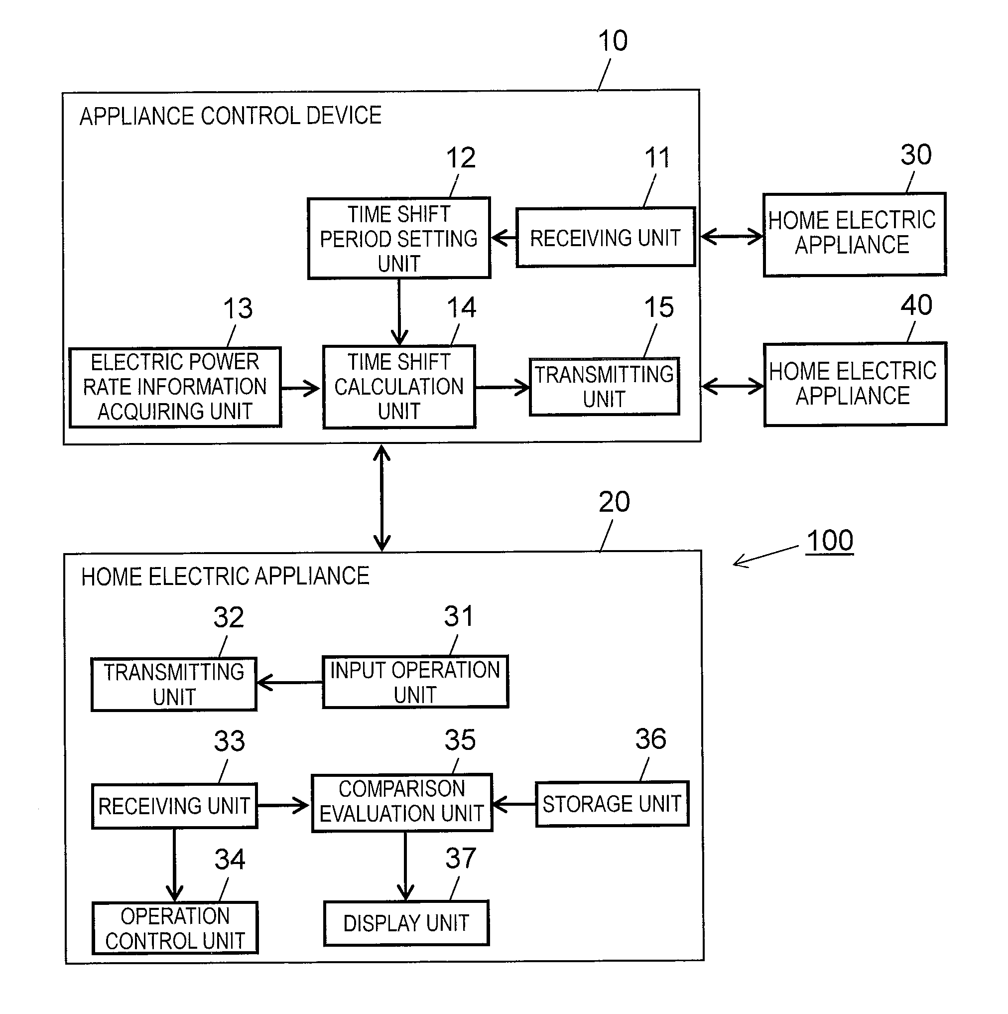
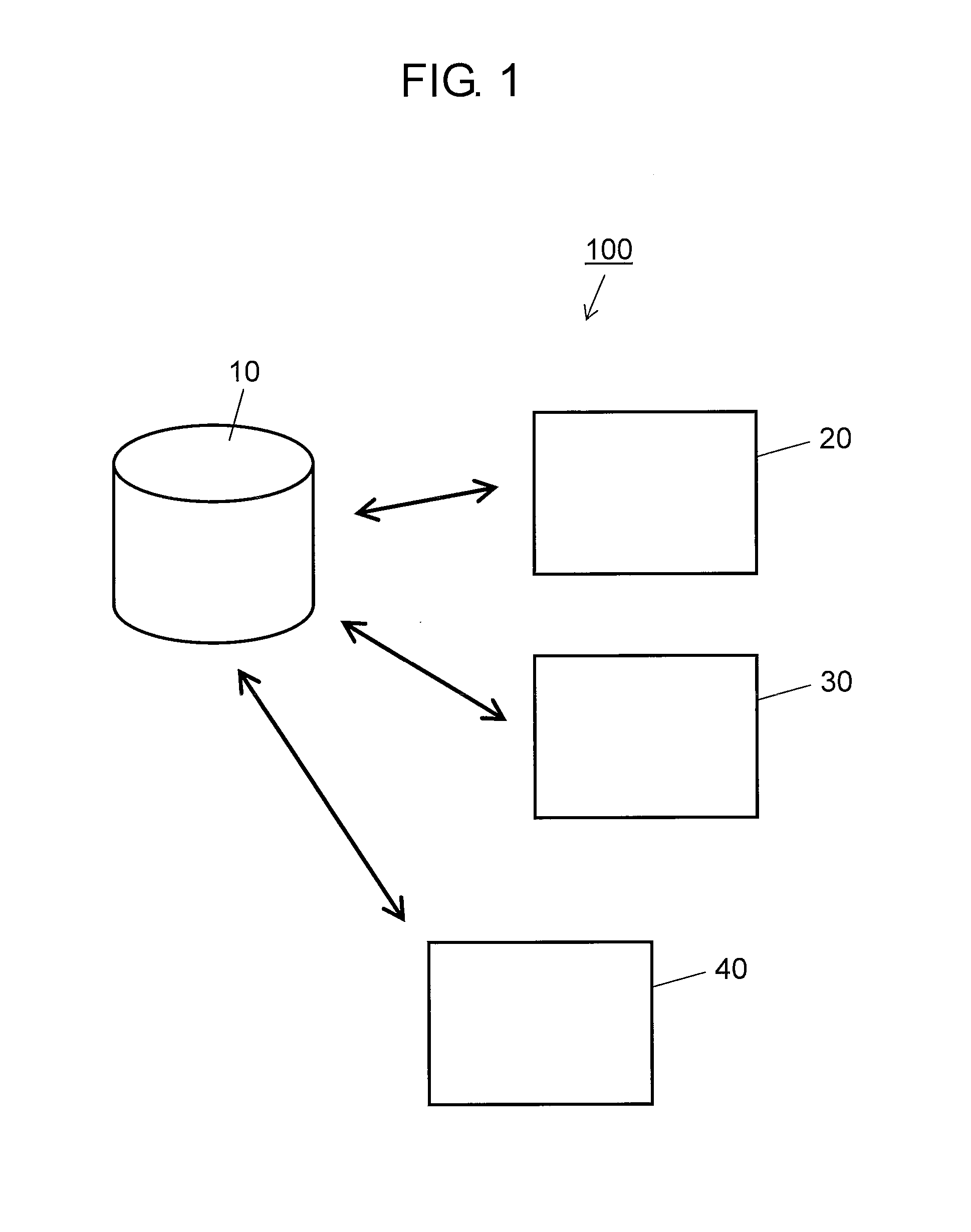
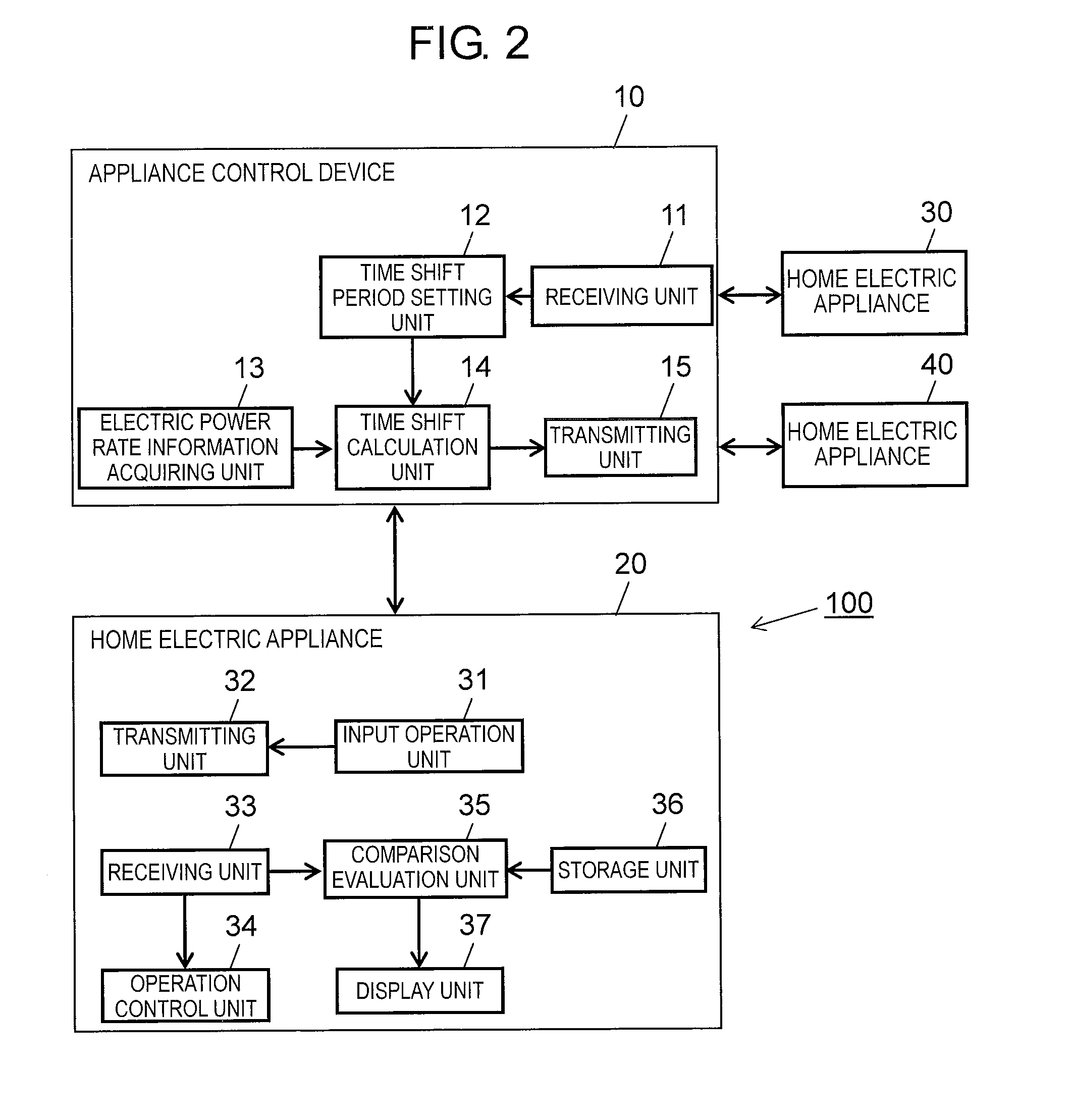
[0036]FIG. 1 is a view for illustrating an outline configuration of an appliance control system in accordance with a first exemplary embodiment of the present invention. Appliance control system 100 shown in FIG. 1 includes appliance control device 10 and home electric appliances 20, 30, and 40.

[0037]In this exemplary embodiment, a washing / drying machine is described as an example of the home electric appliance, but the home electric appliance of the present invention is not necessarily limited to this, and the present invention can be suitably applied to home electric appliances having timer reservation operation functions for both operation start and operation end. Examples of such home electric appliances include an air-conditioner, a washing machine, a laundry dryer, an electromagnetic cooker (IH), an electric water heater, a dishwasher, a rice cooker, a kitchen garbage processor, and the like.

[0038]Appliance control device 10 and home electric appliances 20, 30, and 40 are conn...


PUM


Abstract

A home electric appliance of the present invention includes an input operation unit for inputting desired time information indicating any of a desired operation start time and a desired operation end time; a receiving unit for receiving a time shift calculation result including any of an operation start time and an operation end time and an electricity charge of which an amount becomes not more than a predetermined value when the appliance is operated according to the operation start time or the operation end time within a predetermined period determined by the desired time information; a storage unit for storing a reference value with which the time shift calculation result is evaluated; a comparison evaluation unit for carrying out comparison processing which compares the time shift calculation result with the reference value stored in the storage unit; an operation control unit for controlling operation of the appliance based on the time shift calculation result; and a display unit for displaying information regarding the operation. The display unit changes a display method according to a comparison result by the comparison evaluation unit.

Description

TECHNICAL FIELD[0001]The present invention relates to a home electric appliance in which any of an operation start time and an operation end time is controlled.BACKGROUND ART[0002]Conventionally, there has been proposed an electric load leveling system which presents a time zone in a day during which a load of a power supply device of a power company is low to each customer for promoting use of electric power during the time zone (see, for example, Patent Literature 1).[0003]The above-mentioned electric load leveling system can increase bottom electric power by presenting a time zone (recommended electricity use hours) in a day during which a load of the power supply device is low to each customer for promoting use of electric power during this time zone. Accordingly, reduction of peak electric power of electric power demand can be expected, so that the load of the power supply device can be leveled as a whole.[0004]Furthermore, when the load of the power supply device is leveled, t...

Claims


Application Information

Patent Timeline
Patent Type & Authority Applications(United States)
IPC IPC(8): G05B15/02
CPCG04G15/006G05B15/02Y04S20/242H02J13/0075H02J2003/143H02J3/14H02J2003/146Y02B70/3225Y04S20/224Y02B70/3266H02J13/0006Y04S20/222Y02B90/2653Y04S40/126H02J2310/64H02J2310/14H02J13/00004Y02B70/30Y02B90/20Y02P80/10Y04S50/10Y04S20/00H02J13/00001H02J13/00006Y04S40/12
Inventor KOUDA, TETSUYAIKEDA, TOSIHISAYOSHIMURA, YASUOTAKAYAMA, HISASHIWAKI, YUKI
Owner PANASONIC INTELLECTUAL PROPERTY MANAGEMENT CO LTD
Learn More