
Photocell array tracking device

A technology of tracking device and photovoltaic cell, which is applied in the field of solar energy application, can solve the problem of high cost, and achieve the effect of reducing electricity price, cost and height

Inactive Publication Date: 2011-07-20
余华阳
View PDF0 Cites 3 Cited by
  • Summary
  • Abstract
  • Description
  • Claims
  • Application Information

AI Technical Summary

Problems solved by technology

[0003] For large-scale solar power generation, photovoltaic cells need to be arranged in a square array. The known tracking method is to use two sets of electromechanical drives for each device. A square array is composed of several sets. This requires the use of many motors and reducers, and the cost is too high. high

Method used


Image

  • Photocell array tracking device
  • Photocell array tracking device

Examples


Embodiment Construction

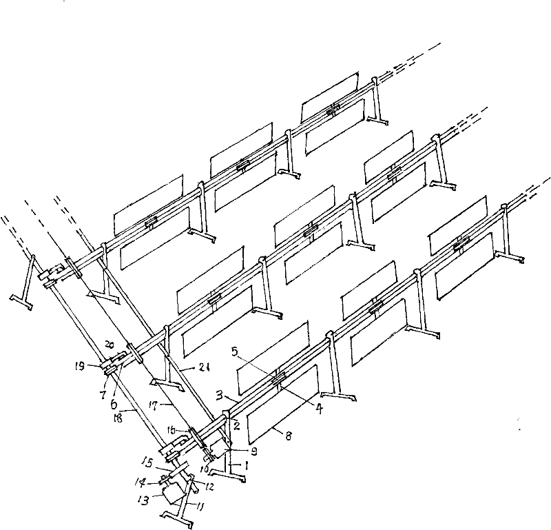
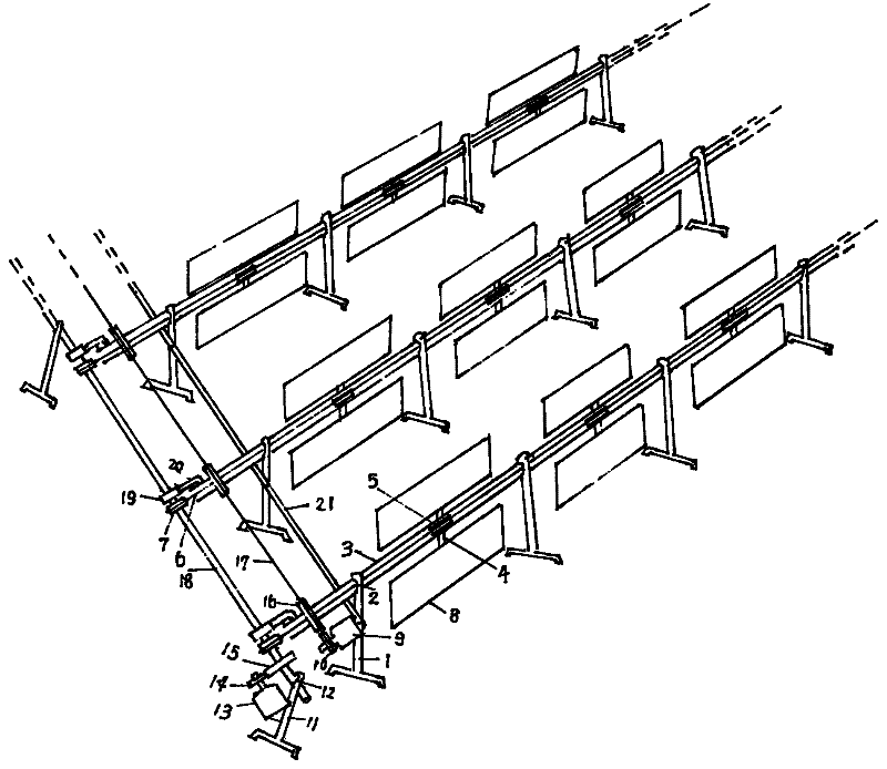
[0009] Fix the long shaft [3] in the upper end bearing [2] of many columns [1], and utilize bearings (not shown in the figure) to fix a plurality of short shafts [4] on the long shaft [3]. ] middle fixed transmission wheel [5], fixed frame [8] at both ends, two pieces are a group, and many groups form a row; Be fixed on the column [1] with a plurality of crossbeams [21] to form a square matrix with multiple rows; Fix the drive wheel [16] on the major axis [3], and make them on a straight line, use the flexible transmission part [17] to sequentially drive the drive wheel [16] and the slow motor [9] fixed on the column [1] The driving wheel [10] at the end is socketed; the transmission shaft [18] is fixed in the upper end bearing [12] of the column [11], and the transmission shaft [18] is fixed on the long axis through the bearing [19] with the fixing piece [20] [3] end; fix the transmission wheel [7] at the position corresponding to the center of the transmission shaft [18] and...


PUM


Abstract

The invention provides a photocell array tracking device which belongs to the field of solar power application. Photocells for large-scale solar power generation are arranged in an array manner. In the prior art, the array is composed of a plurality of tracking devices which are respectively provided with two sets of transmission devices, thus a plurality of motors and gear reducers are needed, resulting in high cost. In the invention, two sets of transmission devices are adopted to drive the array, which comprises the following steps: a photocell frame (8) is fixed at both ends of a stub shaft (4) on a long shaft (3) to constitute a group and a plurality of groups constitute a row; beams (21) are adopted to fix a plurality of rows into the array; and flexible transmission parts (17) are adopted to sequentially sleeve transmission wheels (16) of the long shaft with driving wheels (10) at the end of a motor (9); flexible transmission parts (6) are adopted to sequentially sleeve delivery wheels (7) of a delivery shaft (18) with transmission wheels (5) of the stub shaft (4), thus driven wheels (15) on the delivery shaft (18) are coupled with driving wheels (14) at the end of a motor (13). In the device, two motors are adopted to drive the array and photocells of thousands of square meters track the sun, thus the generation cost is greatly reduced.

Description

[0001] Field [0002] The invention belongs to the field of solar energy application, in particular to a solar tracking device. Background technique [0003] For large-scale solar power generation, photovoltaic cells need to be arranged in a square array. The known tracking method is to use two sets of electromechanical drives for each device. A square array is composed of several sets. This requires the use of many motors and reducers, and the cost is too high. high. Contents of the invention [0004] The object of the present invention is to provide a simpler tracking device for photocells arranged in a square array. [0005] The solution is: fix multiple short shafts on the long shaft fixed in the bearing at the upper end of the column, fix the transmission wheel in the middle of the short shafts, fix the frames at both ends of the short shafts to form a row; array; fix the drive wheel on the long axis, and use flexible transmission parts to sequentially connect the dri...

Claims


Application Information

Patent Timeline
Patent Type & Authority Applications(China)
IPC IPC(8): H02N6/00G05D3/00H02S20/32
CPCY02E10/50
Inventor 余华阳
Owner 余华阳
Learn More