Solar automatic tracking system

An automatic tracking and solar energy technology, which is applied in the field of solar power generation, can solve the problems that the distance between the racks cannot be too large, it cannot be used for installation, and the solar strings are open, so as to enhance safety and adaptability, and improve the wind resistance of the hardware , Improve the effect of tracking efficiency

Inactive Publication Date: 2009-09-02
昆明绿电科技(集团)有限公司
View PDF0 Cites 23 Cited by
  • Summary
  • Abstract
  • Description
  • Claims
  • Application Information

AI Technical Summary

Problems solved by technology

[0003] Problem 1. Since the single-axis system can only rotate in the east-west (longitude) direction to track the sun, the usual single-axis flat-panel system solar panels are fixed horizontally, and the effect is best only around the summer solstice. In other seasons, due to the north-south direction of sunlight The offset angle gradually becomes larger, resulting in the loss of sunlight
At the same time, its large windward area will form a large wind load. In order to resist the damage of the strong wind, the strength requirements of the structural parts must be increased, so that the consumables will increase and the cost will increase.
[0004] Problem 2. When the single-axis system is installed in a row in a large area, due to the land occupation factor, the allowable interval between the racks cannot be too large, so there will be shadows during the tracking process (see the figure below), causing some Open circuit of solar strings affects power output
[0005] Question 3. Since the single-axis system is a multi-column support structure, the fixed bearing seat usually used in the traditional single-axis system can only be installed on the flat ground as a whole frame, and cannot be adapted to a large number of installations on the complex terrain of mountainous areas with unevenness and different slopes. use

Method used


Image

  • Solar automatic tracking system
  • Solar automatic tracking system
  • Solar automatic tracking system

Examples


Embodiment approach

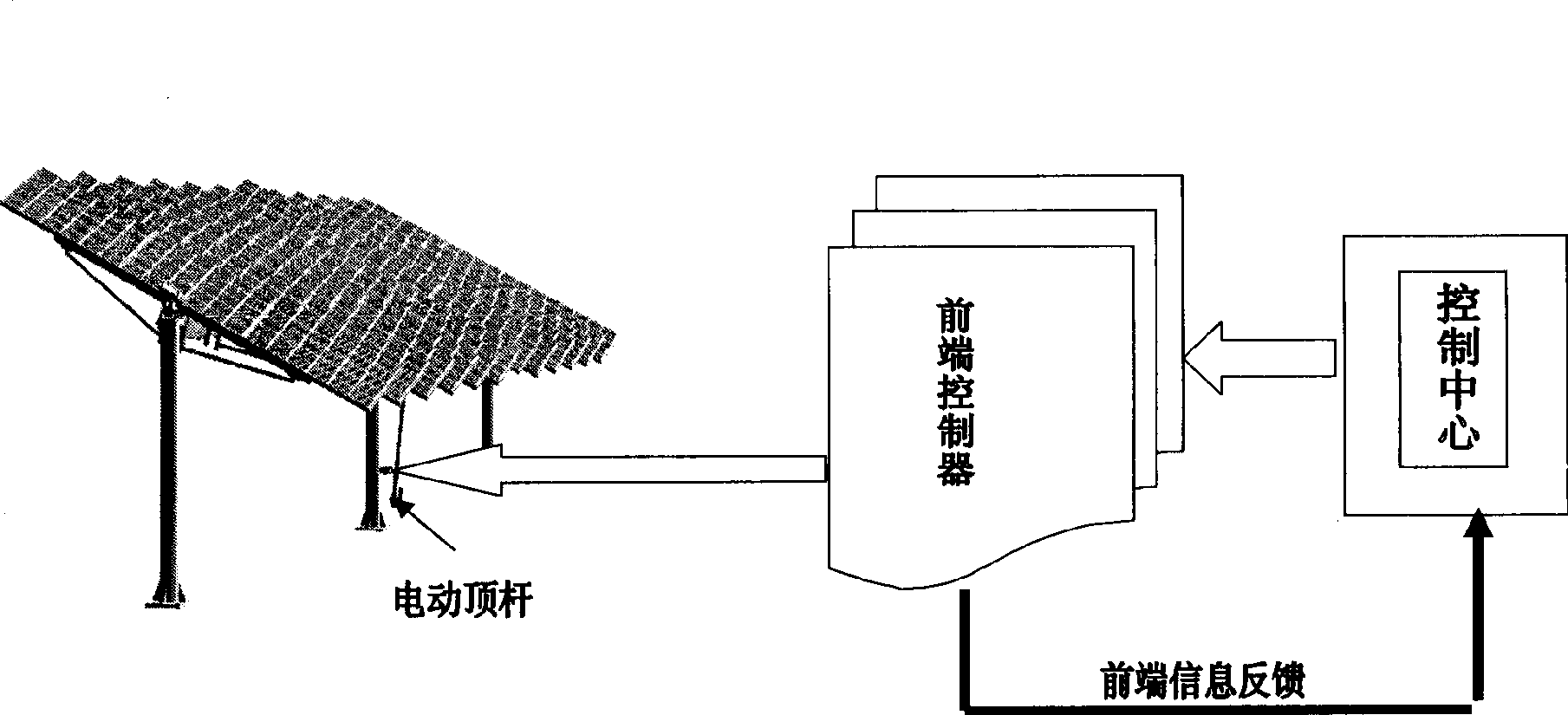
[0068] The control system is composed of control circuit, tracking control module and so on.

[0069] Among them, the control circuit is composed of a control center, a partition controller, a front-end controller, and an electric ejector rod. The control center is the brain of the entire solar automatic tracking system, which can display the real-time status of all solar matrix racks in the entire control area in real time. Including: running posture, real-time angle of the current battery panel, the state of the sun (illuminance), sunrise and sunset time of the day, working status of each hardware device of the control system, etc. According to the astronomical information obtained from the database, the attitude control data of solar panels in different seasons in spring, summer, autumn and winter can be formulated, and sent to each control front end to implement automatic tracking control. Its partition controller plays a linking role in the control system. The master co...


PUM


Abstract

The invention discloses a solar automatic tracking system comprising hardware which has a smart structural design with single-axle scaly solar panels (1) and a universal joint bearing seat (5), and the solar automatic tracking system is suitable for a shaft support with multiple pillars, is mounted in complex hilly lands, has down-moved gravity of the support and flexible turning and enables the system to adopt a single-axis tracking system to establish a solar power station in bumpy hilly lands, thereby ensuring that the solar panels always obtain solar radiation energy as much as possible in the hilly lands, enhancing the tracking efficiency, effectively improving the anti-wind capability of the hardware, reducing the material breakage brought by windage resistance and strengthening the security and the adaptability. With a unique shadow elusion system processing function, the system prevents the solar panels on a stand from generating energy degradation because of being sheltered from mutual shadows and enables the solar panels to obtain the greatest energy output, thereby not only improving the solar electrical energy generation efficiency greatly, but also enhancing the adaptability of the solar tracking system and saving the limited resources by saving occupied space about 50 percent compared with the prior solar tracking system.

Description

1. Technical field [0001] The invention relates to solar power generation technology, in particular to a solar automatic tracking system for a large-scale solar power station with a relatively large area. 2. Background technology [0002] We know that only when the sun's rays shine directly on the solar panel, the panel can get the maximum power output. In order to improve the efficiency of solar panel power generation, it is an effective choice to use a solar tracking mounting system. Its function is to make the surface of the solar cell array automatically track and rotate as the sun moves in the sky, and try to keep it facing the sun vertically. At present, the solar panel support of the solar tracking system usually adopts a single-axis structure, and the solar panel installation method of the system is flat, that is, all the panels are fixed on a large horizontal frame. The traditional single-axis system has the following three problems: [0003] Problem 1. Since the...

Claims


Application Information

Patent Timeline
Patent Type & Authority Applications(China)
IPC IPC(8): H02N6/00G05D3/00H02S20/32
CPCY02E10/50
Inventor 曹锐傅其中汪福才
Owner 昆明绿电科技(集团)有限公司
Why Eureka
Try Eureka