PEM fuel cell stack

a fuel cell and stack technology, applied in the direction of fuel cells, propulsion by batteries/cells, electric vehicles, etc., can solve the problems of obstructing the gas transport and impairing the electrical output of the fuel cell, and achieve the effect of improving the transport properties and water content, and further reducing the obstruction of the gas flow in the channel

Inactive Publication Date: 2004-04-13
UMICORE AG & CO KG +1
View PDF13 Cites 20 Cited by
  • Summary
  • Abstract
  • Description
  • Claims
  • Application Information

AI Technical Summary

Benefits of technology

According to the invention the cell resistance (resistance of an individual membrane electrode assembly) is reduced by defined compression of the woven gas distribution layers. The aim is preferably to achieve compression of the gas distribution layers to 30 to 50, particularly 35 to 40% of their original thickness D.sub.1. Experience has shown that the specific resistance of the carbon fiber fabric can be reduced to below 6 m.OMEGA.cm by compression. The porosity of the gas distribution layer is also reduced to 20 to 70% of the original porosity, thereby preventing flooding of the pores with reaction water. Both effects lead to a decisive improvement in the electrical output of the fuel cell stack.
The fact that the defined compression of the gas distribution layers avoids the need for the otherwise conventional provision of the gas distribution layers with an electrically conductive microporous layer and the associated complex process steps is particularly advantageous. Moreover, there is also no need for the use of a special support plates intended to prevent penetration by the carbon fiber fabric of the gas distribution layers into the flow channels on the bipolar plates.
A particularly advantageous embodiment of the PEM fuel cell stack according to the invention is obtained if the weave direction of the carbon fiber fabric from which the gas distribution layers are made is turned at an angle .alpha. of 20 to 70, preferably 30 to 60, and particularly of 45.degree. to the flow channels on the bipolar plates, or if the carbon fiber fabric is woven in a structure such that at least 60% of the fibers exhibit an angle of at least 30.degree. to the channel structure of the bipolar plates. In this case a further improvement of the transport properties and water content of the gas distribution layers is obtained, since penetration of the fabric into the gas distribution channels and hence obstruction of the gas flow in the channels is further reduced. The same positive effect is also obtained if the gas distribution channels are arranged in a suitable pattern on the bipolar plates.
The PEM fuel cell stacks according to the invention display good access by the reactive gases to the catalytically active centers of the membrane electrode assemblies, effective humidifying of the ionomer in the catalyst layers and the membrane and straightforward removal of the reaction product water from the cathode side of the membrane electrode assemblies.

Problems solved by technology

This involves the risk that the flexible gas distribution layers will penetrate into the gas distribution channels open on one side, thereby obstructing the transport of gas and impairing the electrical output of the fuel cell.

Method used


Image

  • PEM fuel cell stack
  • PEM fuel cell stack
  • PEM fuel cell stack

Examples


example 1

Carbon fiber fabric type AvCArb 1071 HCB from Textron Inc. with a weight per unit area of 115 g / m.sup.2 and a thickness of 380 .mu.m was immersed in a suspension of PTFE in water (Hostaflon TF5235, Dyneon GmbH). The material was removed after a few seconds. After allowing the suspension adhering to the surface to drip off, the carbon fiber fabric was dried in a circulating air drying oven at 100.degree. C. The impregnated carbon fiber fabric was sintered in a chamber furnace at 340 to 350.degree. C. for approx. 15 minutes to melt the PTFE incorporated into the structure.

By adjusting the PTFE concentrations in the suspension, carbon fiber papers were produced with a PTFE content of 14.5.+-.0.5 wt. % for the anode and 6.5.+-.0.5 wt. % for the cathode of a fuel cell.

The average thickness of the finished carbon fiber fabric was 330 .mu.m.

These anode and cathode gas distribution layers were incorporated along with a catalyst-coated membrane according to comparative example 1 into a fuel ...

example 2

The carbon fiber fabrics were hydrophobed and sintered as in example 1. The PTFE content was 14.5.+-.0.5 wt. % for the anode and 6.5.+-.0.5 wt. % for the cathode.

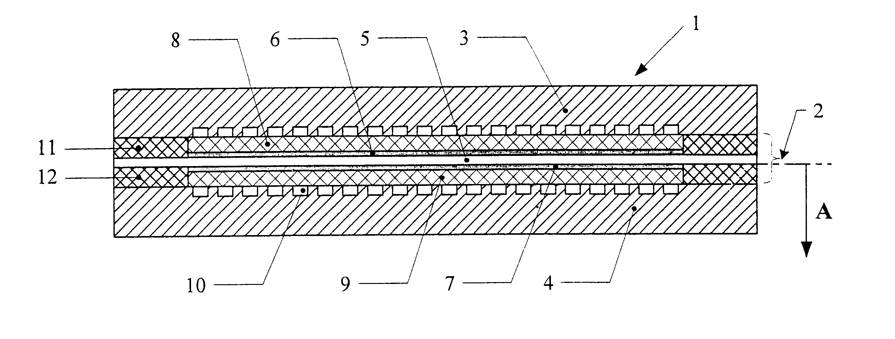
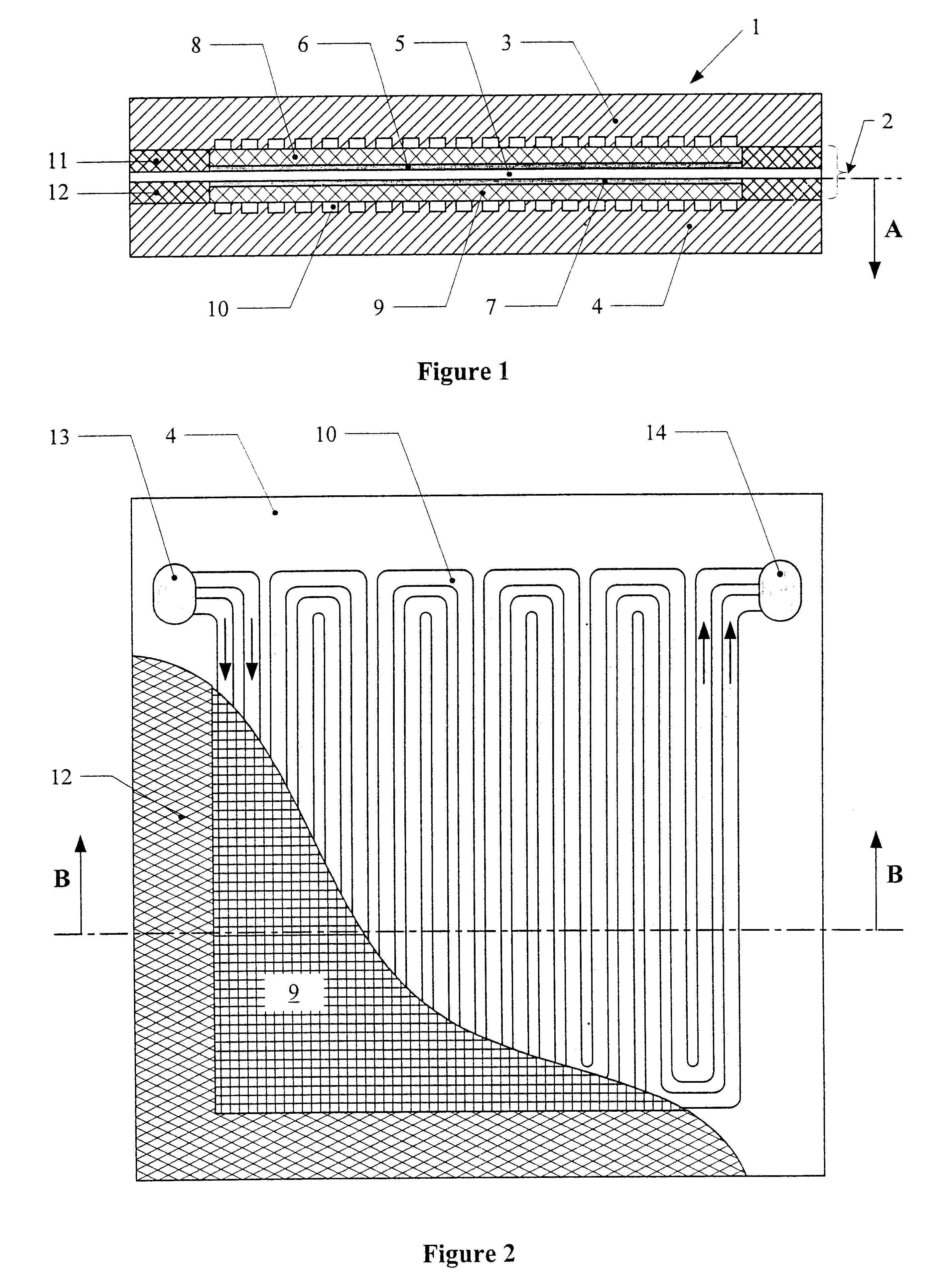
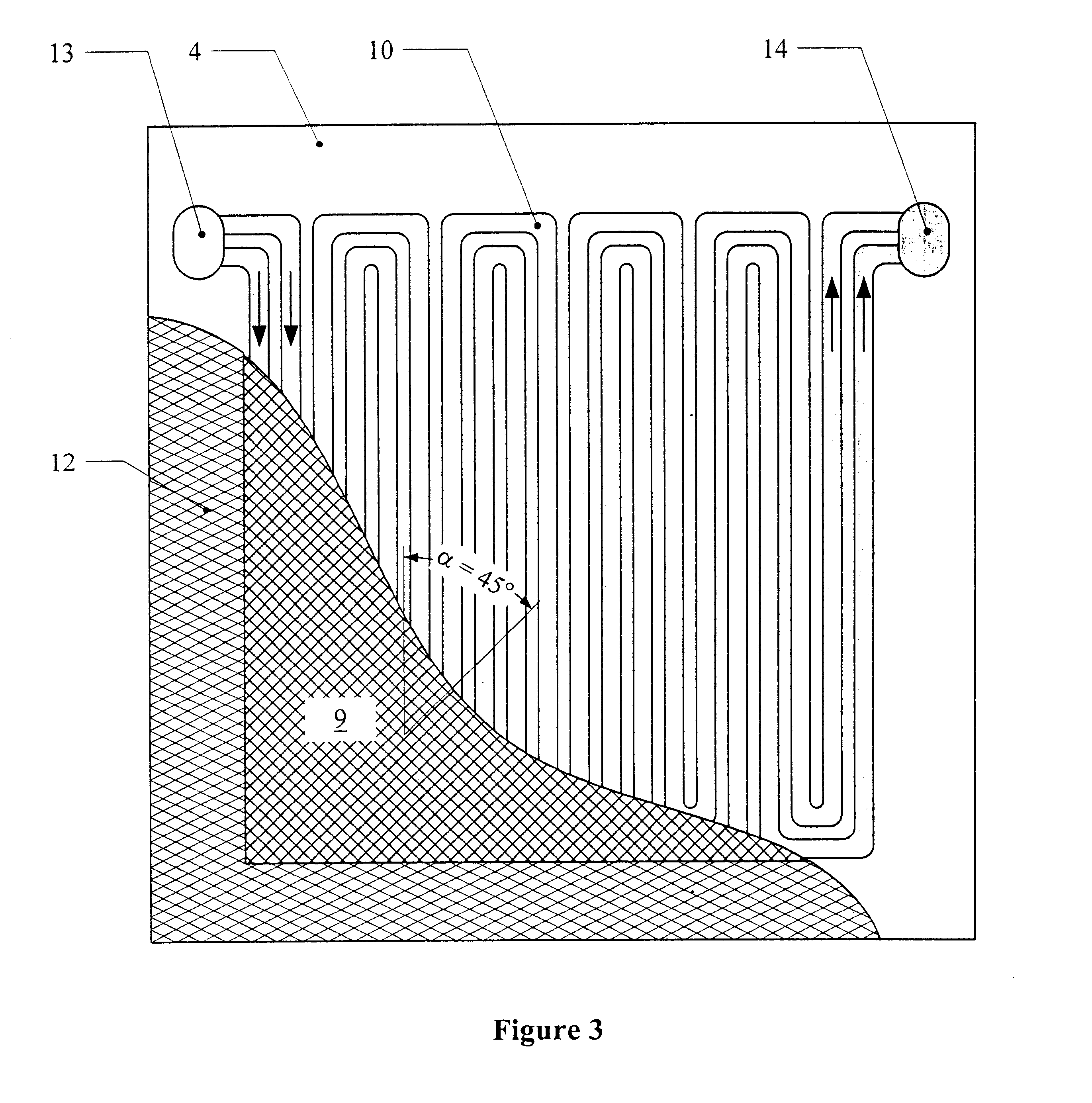
These anode and cathode gas distribution layers were incorporated together with a catalyst-coated membrane according to comparative example 1 into a fuel cell test cell with a double serpentine structure. The fabric was oriented such that the cross weave was positioned at an angle .alpha. of 45.degree. to the direction of the gas distribution channels. In assembling the test cell the bipolar plates were screwed together so tightly that the gas distribution layers including the catalyst layer were compressed to the thickness of the seals.

Two Chemglas seals (non-compressible, glass fiber-reinforced PTFE, 0.14 mm thick) with an overall thickness of 0.28 mm were used as seals. Together with a thickness for the catalyst layer of 20 .mu.m, this results in a compression of the gas distribution layers to 36.4% of their original thi...

examples 1 and 2

show an improved output in comparison with comparative examples 2 and 3. There is even a slight output advantage at low and high current densities in comparison to the gas distribution layers coated with a carbon black / PTFE microporous layer as described in comparative example 1. The main advantage in this case, however, is that the complex production of the carbon black / PTFE microporous layer is avoided. Further variations and modifications of the foregoing will be apparent to those skilled in the art and are intended to be encompassed by the claims appended hereto. German priority application 100 42 744.8 of Aug. 31, 2000 is relied on and incorporated herein by reference.


PUM

PropertyMeasurementUnit
angleaaaaaaaaaa
angleaaaaaaaaaa
angleaaaaaaaaaa

Abstract

A PEM fuel cell stack including one or more fuel cells (1) arranged on top of one another, each of which contains a membrane electrode assembly (2) between two electrically conductive bipolar plates (3,4), the surfaces of which are equipped with flow channels (10) open on one side for the supply of reactive gases, whereby the membrane electrode assemblies each comprise a polymer electrolyte membrane (5), both sides of which are in contact with a reaction layer (6,7), whereby the surface area of the reaction layers is smaller than that of the polymer electrolyte membrane and a compressible, coarse-pore gas distribution layer (8,9) made from carbon fiber fabric is inserted between each reaction layer and the adjacent bipolar plates congruent to the reaction lawyers along with seals (11,12) in the area outside the surface covered by the gas distribution layers, whereby the gas distribution layers in the no-load condition display a thickness D1 and the seals a thickness D2. The PEM fuel cell stack is featured by the gas distribution layers in the PEM fuel cell stack being compressed to 25 to 60% of the original thickness.

Description

INTRODUCTION AND BACKGROUNDThe present invention concerns a PEM fuel cell stack consisting of membrane electrode assemblies, gas distribution layers and bipolar plates stacked one above the other. The invention particularly concerns PEM fuel cell stacks containing gas distribution layers consisting of woven carbon fibers.Fuel cells convert a fuel and an oxidizing agent, which are locally separated from one another at two electrodes, into electricity, heat and water. Hydrogen or a hydrogen-rich gas can be used as the fuel, oxygen or air as the oxidizing agent. The process of energy conversion in the fuel cell is characterized by a particularly high efficiency. For this reason fuel cells in combination with electric motors are gaining growing importance as an alternative to conventional combustion engines.The compact design, power density and high efficiency of so-called polymer electrolyte fuel cells (PEM fuel cells) make them suitable for use as energy converters in electric cars.In...

Claims


Application Information

Patent Timeline
Patent Type & Authority Patents(United States)
IPC IPC(8): B60L11/18H01M4/86H01M2/14H01M4/96H01M8/10H01M8/00H01M8/02H01M8/24H01M8/0234H01M8/0263H01M8/0273H01M8/0282H01M8/1007H01M8/242H01M8/248
CPCH01M8/0234H01M8/0263H01M8/1002B60L11/1898H01M8/0273H01M8/0282H01M8/2405H01M8/242H01M8/248Y02E60/521B60L2240/36Y02T90/34H01M8/1007B60L50/72Y02T90/40Y02E60/50H01M8/2457H01M8/02H01M8/0271
Inventor ZUBER, RALFBAYER, ARMINKUHNHOLD, HEIKESTENKE, UDO
Owner UMICORE AG & CO KG
Why Eureka
Try Eureka