Load management auxiliary power system

a technology of auxiliary power system and load management, which is applied in the direction of transportation and packaging, light and heating equipment, laminated elements, etc., can solve the problems of insufficient area, increased normal maintenance costs of the truck engine and its associated system, and staggering fossil fuel waste in the trucking industry. , to achieve the effect of maximizing the load placed on the auxiliary engin

Inactive Publication Date: 2005-08-04
KENNEDY GINO
View PDF16 Cites 19 Cited by
  • Summary
  • Abstract
  • Description
  • Claims
  • Application Information

AI Technical Summary

Benefits of technology

[0016] The instant invention system includes a small diesel engine coupled to an air conditioner compressor, a generator or alternator and a combination control relay / regulator for maximizing the loads placed on the auxiliary engine. The truck operator is provided with controls for selective operation of the auxiliary power system's various features which may be operated while the truck's main engine is running or stopped.
[0019] During hot weather operation the driver may utilize the controls to start the auxiliary engine. The auxiliary engine may then be utilized to operate an air conditioner compressor and related air conditioner system components, wherein the truck interior is kept cool. During this mode the auxiliary engine is also utilized to operate the alternator or generator to replenish power drawn from the truck batteries. In order for the auxiliary engine to provide power for both accessories, a control relay / regulator is utilized to switch the input field of the alternator, thereby reducing alternator output to maximize the power output of the auxiliary engine. Should the truck accessories draw more electrical power than the alternator or generator supply during such a peak demand, the truck batteries operate as a reserve power source. When the air conditioning compressor cycles off, the control relay / regulator causes the alternator or generator to increase electrical output to replenish the truck batteries and supply electrical power to other accessories. In this manner the power output provided by the auxiliary engine may be more fully utilized than in prior art power systems.
[0026] Yet another objective of the invention is to teach the use of an auxiliary power system that is inexpensive, small in size and lightweight.

Problems solved by technology

Total fossil fuel waste, and the associated economic waste, within the trucking industry is staggering.
In addition to the cost of the diesel fuel, normal maintenance costs to the truck engine and its associated systems are increased.
Problems generally associated with the use of these prior art devices relate to size, weight, and placement of the systems.
If the overall dimensions are too large, there will be insufficient areas on a truck for which to place the system.
Other problems result from complexity of installation and the costs associated therewith.
Still other problems result from sharing coolant systems.
Small engines rarely generate enough heat to maintain temperature within a large cooling system such as those supplied with a large truck.
As a result of the constant cold cylinder temperature the small engine runs inefficiently.
However, the false loads and oversized engines decrease the overall efficiency of these systems.
Other problems and expense are incurred with the use of water-to-water or water-to-oil heat exchangers.
The heat exchangers are expensive, difficult to install, and require each body of fluid to be equipped with an independent pump for fluid circulation.
None of the prior art devices disclose or teach a system which is constructed to utilize a minimally sized engine to prioritize and drive alternative loads.
Thus, what is needed is an auxiliary power system that is lightweight, consumes a small space, and may be used to alternatively provide heating, electrical power or air conditioning to the interior of a truck.

Method used


Image

  • Load management auxiliary power system
  • Load management auxiliary power system
  • Load management auxiliary power system

Examples


Embodiment Construction

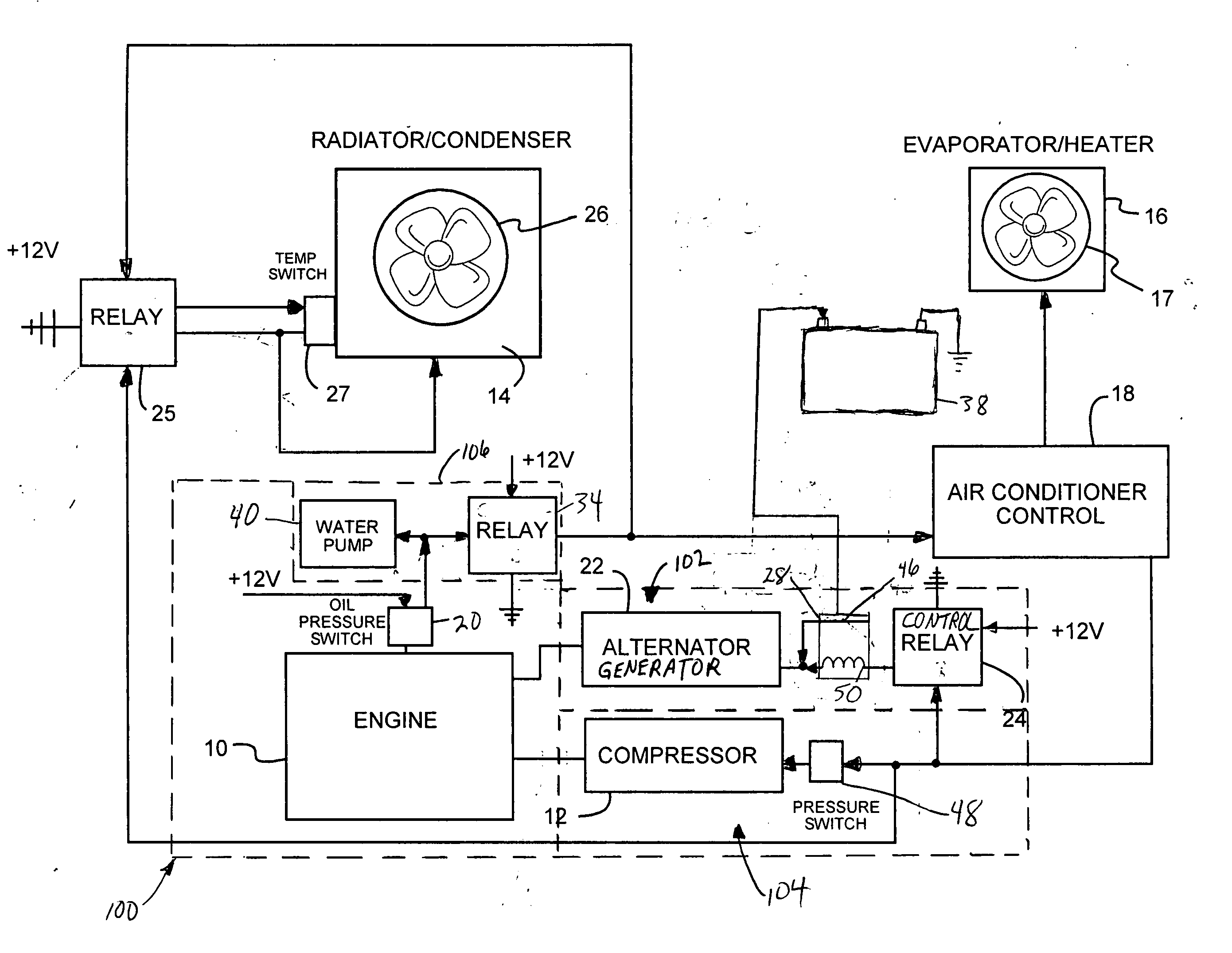
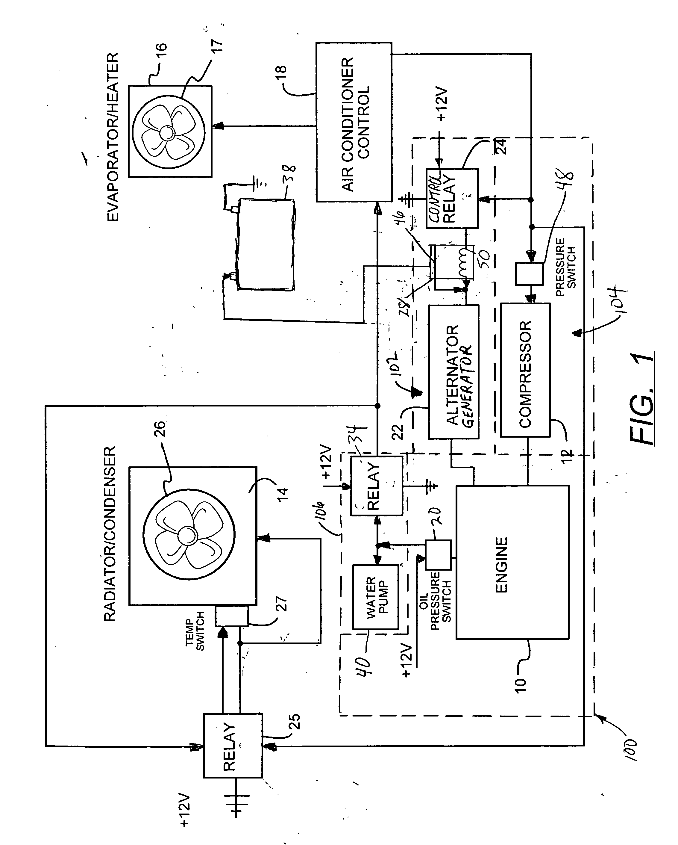
[0031] Now referring to FIG. 1, a diagrammatic representation of one embodiment of the instant invention auxiliary power system 100 is illustrated. The auxiliary power system generally includes an auxiliary engine 10 for selectively providing power to an electrical generation system 102, an air conditioning system 104, and a heating system 106. In the preferred embodiment the auxiliary engine is sized so that it is not capable of simultaneous operation of the air conditioning system and the electrical generation system to their respective full capacities. The auxiliary power system includes a unique control relay / regulator combination 24, 28 for reducing electrical power produced by the electrical generation system 102 during simultaneous operation of the air conditioning system 104. This construction and arrangement permits the size and weight of the auxiliary power system to be substantially smaller than the power systems of the prior art. The arrangement also permits the auxiliar...


PUM


Abstract

An auxiliary power system for trucks, the power system having a small diesel engine coupled to an air conditioner compressor and an automotive style alternator. During hot weather the auxiliary engine rotates the air conditioner compressor to provide cool air to the truck and electrical power to truck accessories by load management controls. When peak loads occur, the voltage is reduced into the field of the alternator allowing the small engine to simultaneously operate the air conditioning compressor. During cold weather the engine coolant is used to cool the auxiliary engine and is circulated through a heat exchanger for warming of the truck interior. Full capacity of the alternator is allowed, accommodating the higher amp draws typical of cold weather diesel operation.

Description

RELATED APPLICATIONS [0001] This application is a continuation-in-part of applicant's co-pending U.S. application Ser. No. 10 / 060,091 filed Jan. 29, 2002, the contents of which are hereby incorporated by reference.FIELD OF THE INVENTION [0002] This invention is related to auxiliary power systems, in particular, to an auxiliary power system having a load shedding voltage regulator which prioritizes air conditioning by reducing electrical power generation to minimize auxiliary engine size requirements, thus reducing space and weight requirements for the auxiliary power system. BACKGROUND OF THE INVENTION [0003] Total fossil fuel waste, and the associated economic waste, within the trucking industry is staggering. It is estimated that six out of every fourteen hours of truck operation are spent idling. Federal and State laws alike limit the number of hours that each truck driver can legally drive a truck in a twenty-four hour period. During the remainder of the time the driver must res...

Claims


Application Information

Patent Timeline
Patent Type & Authority Applications(United States)
IPC IPC(8): B60H1/00B61D27/00
CPCB61D27/00B60H1/00421
Inventor KENNEDY, GINO
Owner KENNEDY GINO
Why Eureka
Try Eureka