
Method for hybrid solar tracking, and apparatus for hybrid solar tracking and photovoltaic blind system using same

a technology of solar tracking and hybrid solar energy, applied in the direction of solar heat collector controllers, mechanical power/torque control, electric power measurement, etc., can solve the problems of not necessarily ensuring the maximum output of generated power, not necessarily ensuring the maximum of generated power, and not necessarily ensuring the largest power production, so as to achieve the effect of maximizing photovoltaic power outpu

Inactive Publication Date: 2016-06-30
IND ACADEMIC CORP FOUND YONSEI UNIV
View PDF3 Cites 13 Cited by
  • Summary
  • Abstract
  • Description
  • Claims
  • Application Information

AI Technical Summary

Benefits of technology

The present invention provides a method and apparatus for solar tracking, and a photovoltaic blind system that can maximize photovoltaic power output without using optical sensors. This is achieved by brilliantly interweaving an approach of solar tracking based on power output data and an approach of solar tracking based on location and time. The technical effect is an improved method for solar tracking that can increase photovoltaic power output.

Problems solved by technology

Accordingly, the approach requires optical sensors and further a means for determining direction of the sun from the detected signals of the optical sensors, and thus higher costs.
However, due to the features of the blind system, orientation toward the sun does not necessarily ensure maximizing output of generated power.
Furthermore, generally, the wavelength range in which optical sensors are most sensitive does not coincide with the wavelength range in which actual power production gets large, and thus the identified direction of the sun does not necessarily guarantee the largest power production.
Moreover, with bad weather conditions, erroneous operation of optical sensors is inevitable.
Accordingly, -effectiveness to cost thereof can be rather poor.
Although this approach is inexpensive because optical sensors are not required and insensitive to weather conditions, this method suffers from being difficult for implementation.
Although this location and time-based method is also inexpensive because optical sensors are not required and also insensitive to weather conditions, this method suffers from low accuracy.

Method used


Image

  • Method for hybrid solar tracking, and apparatus for hybrid solar tracking and photovoltaic blind system using same
  • Method for hybrid solar tracking, and apparatus for hybrid solar tracking and photovoltaic blind system using same
  • Method for hybrid solar tracking, and apparatus for hybrid solar tracking and photovoltaic blind system using same

Examples


Embodiment Construction

[0048]As to embodiments of the present invention disclosed herein, specific structural and functional descriptions are given merely for the purpose of illustrating the embodiments of the present invention. Embodiments of the present invention may be practiced in various forms, and the present invention should not be construed as being limited to the embodiments disclosed herein.

[0049]Embodiments of the present invention will be described in detail below with reference to the accompanying drawings. The same reference symbols will be used to denote the same components throughout the accompanying drawings, and redundant descriptions of the same components will be omitted.

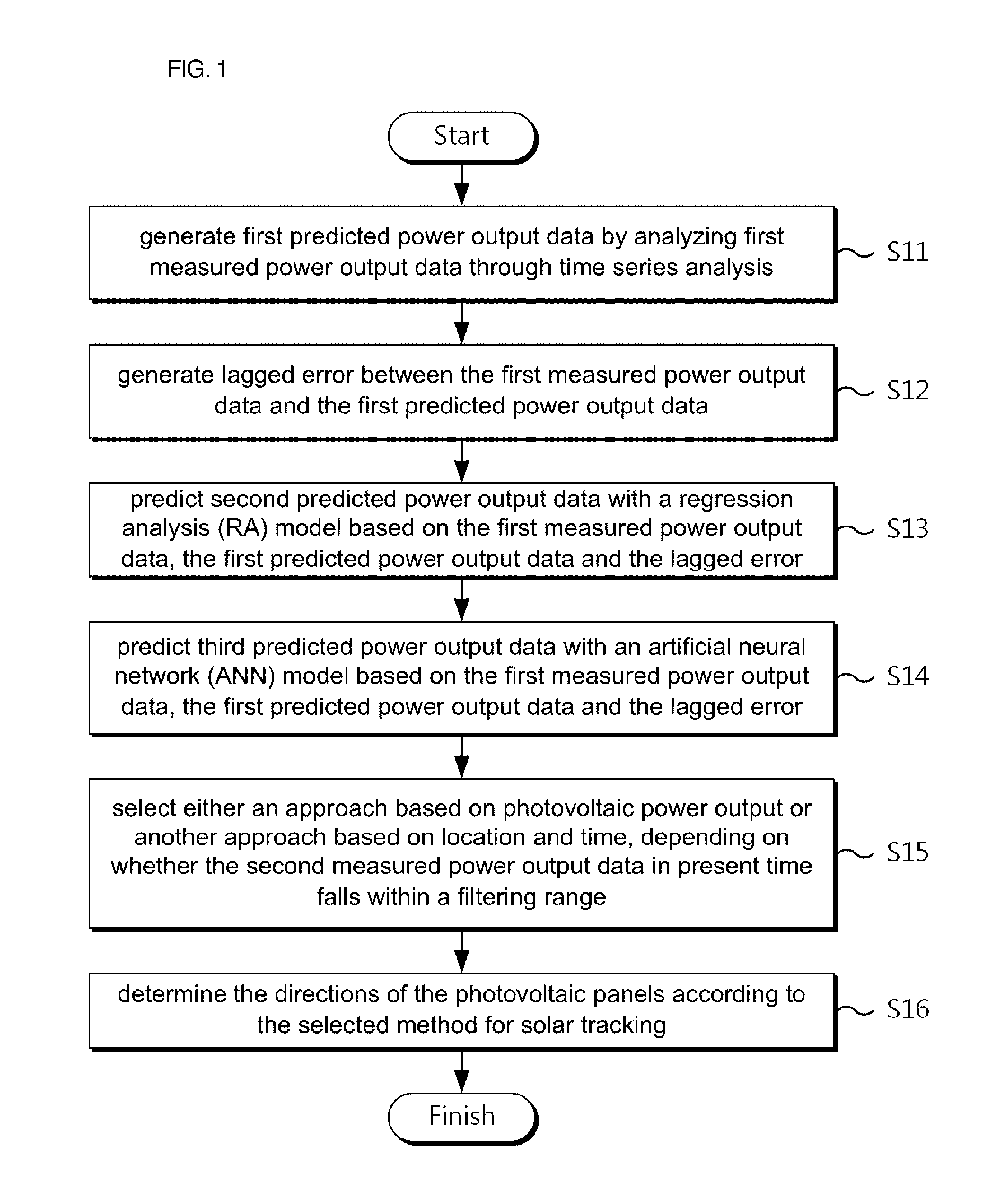
[0050]FIG. 1 is a flowchart illustrating a method for hybrid solar tracking according to embodiments of the present invention.

[0051]Referring to FIG. 1, the method for hybrid solar tracking using a computer according to embodiments of the present invention may start with performing step S11 by a computer as below.

[0052...


PUM


Abstract

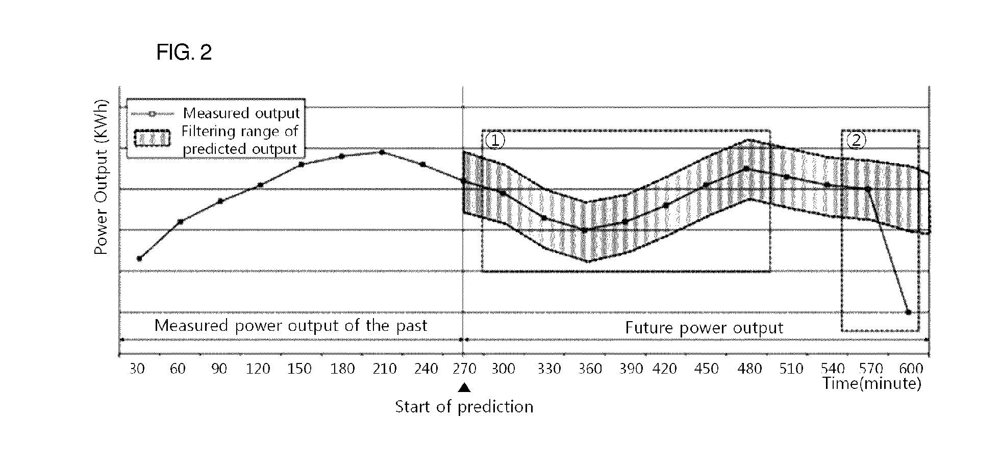
A method for hybrid solar tracking, and an apparatus for hybrid solar tracking and a photovoltaic blind system using the same are disclosed. The method includes generating first predicted power output data by analyzing first measured power output data of the past; generating a lagged error; constructing a regression analysis (RA) model, and deriving second predicted power output data; constructing an artificial neural network (ANN) model, and deriving third predicted power output data; selecting either a method for solar tracking based on photovoltaic power output or a method for solar tracking based on location and time depending on whether the second measured power output data of the present time falls within a filtering range based on a first error range and a second error range; and determining the directions of photovoltaic panels according to the selected method for solar tracking.

Description

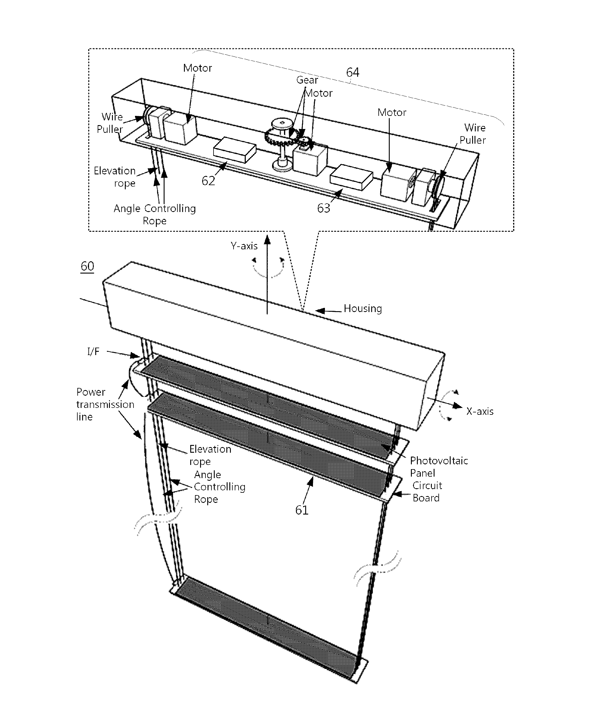
CROSS -REFERENCE TO RELATED APPLICATION(S)[0001]This application claims the benefit under 35 USC 119(a) of Korean Patent Application No. 1 0-201 4-01 96084 filed on Dec. 31, 2014 in the Korean Intellectual Property Office, the entire disclosure of which is incorporated herein by reference for all purposes.BACKGROUND[0002]1. Field[0003]The present invention relates to a photovoltaic blind system.[0004]2. Description of the Related Art[0005]Photovoltaic power generation may be implemented in various forms because this type of power generation does neither entail noise, nor require special geographical features and a wide site, compared to other types of renewable energy generation. Of these various forms, technology for a building integrated photovoltaic (BIPV) system in which photovoltaic power generation panels are installed on a building has been developed.[0006]A BIPV system may have a structure that is combined with a component of a building, such as a roof, a glass window, or th...

Claims


Application Information

Patent Timeline
Patent Type & Authority Applications(United States)
IPC IPC(8): H02S20/32G05B13/04H02S50/00F24S50/20
CPCH02S20/32G05B13/048H02S50/00Y02B10/10E06B9/26G05F1/67H02S20/26H02S20/22G06N3/02Y02A30/24Y02B80/00Y02E10/56Y04S10/50Y02E40/70E06B9/24G01R21/00G01S3/781G01S3/7861E06B2009/2476
Inventor HONG, TAE HOONKOO, CHOONG WANJEONG, KWANG BOKKIM, JI MINBAN, CHEOL WOOLEE, MIN HYUNJI, CHANG YOON
Owner IND ACADEMIC CORP FOUND YONSEI UNIV
Learn More