Offshore wind turbines and deployment methods therefor

a deployment method and wind turbine technology, applied in wind energy generation, wind motors with parallel air flow, liquid fuel engine components, etc., can solve problems such as the shakedown of offshore wind turbines in big storms

Inactive Publication Date: 2014-06-03
WEAVER LLOYD E
View PDF8 Cites 15 Cited by
  • Summary
  • Abstract
  • Description
  • Claims
  • Application Information

AI Technical Summary

Benefits of technology

[0007]1. Enhanced capacity factor by 30% by increasing generator size 50% at a low marginal cost; other infrastructure (tower, blades etc.) are unchanged.
[0039]5. Because it is a downwind turbine, savings occur not only because a smaller lower cost yaw drive is needed, but also a downwind turbine stays better aligned than upwind turbines maximizing power output. Also, upwind turbine controls execute a downwind blade orientation in big storms, but since real data shows essentially no difference in efficiency compared to an upwind turbine, this invention standardizes on a downwind design.

Problems solved by technology

Without this feature, offshore turbines in big storms could shake to pieces.

Method used


Image

  • Offshore wind turbines and deployment methods therefor
  • Offshore wind turbines and deployment methods therefor
  • Offshore wind turbines and deployment methods therefor

Examples


first embodiment

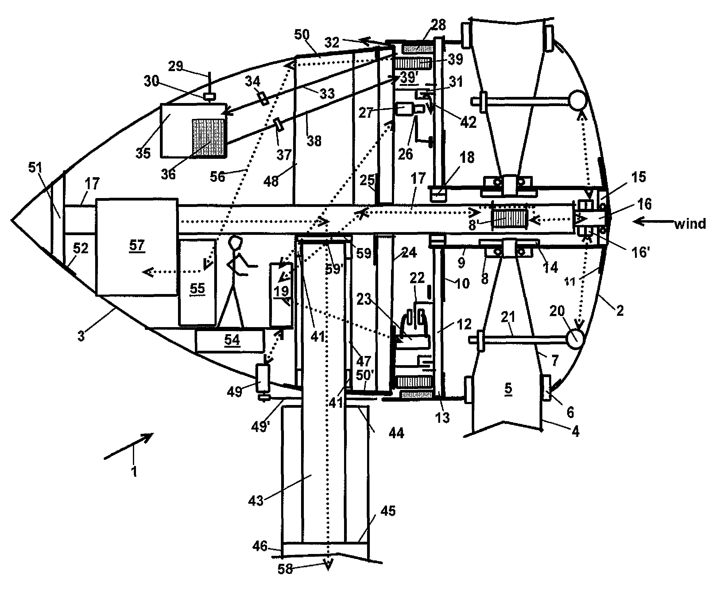
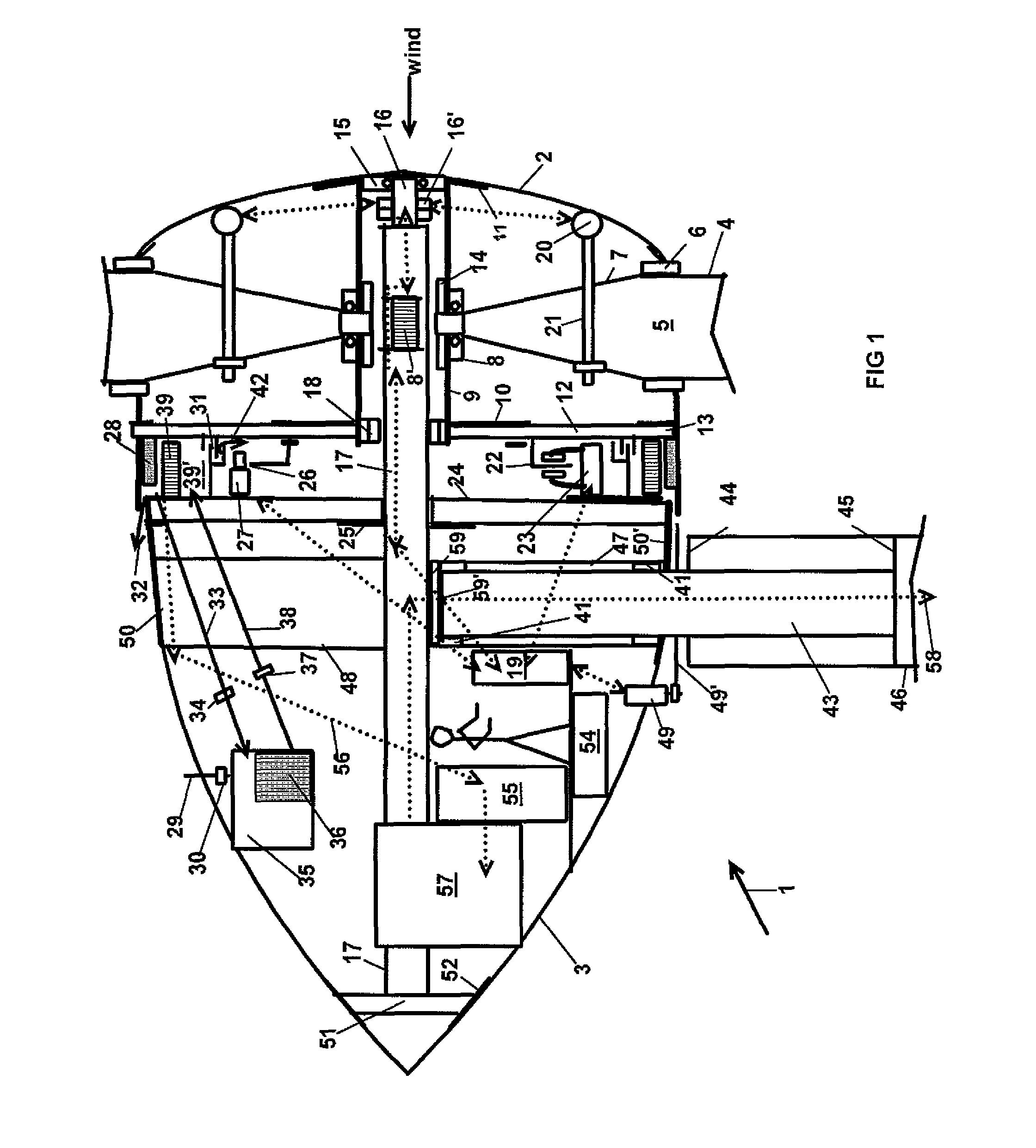
[0067]FIG. 8 depicts an alternative version of the spade method of attaching a blade to the hub by inserting the spade ends 25 of blades 24 of FIG. 8 into scabbard 26. While the spade end of blade 24 is similar to the arrangement of the first embodiment, scabbard 26 makes installing the pin easier, and the pitch adjusting actuator can then be factory assembled and calibrated. Thus, to install blades 24, hub 32 as before has greased plastic journal bearings 27, and end roller bearings 28 that secure scabbard 26, absorbing all forces. Spade end 25 of blade 24 has a hole for pin 29 that passes though scabbard 26 and is retained in position using a plate 29′ in a slot cut into pin 29 as shown, with 29′ cap screwed into tapped treads in the side of 26 or welded to 26 or both. Generator access openings 30 provide access to various areas such as the winch and pin operations shown. Winch 31 is used to pull the tapered spade end 25 of blade 24 into alignment to pin 29 openings. Hub maintenan...

second embodiment

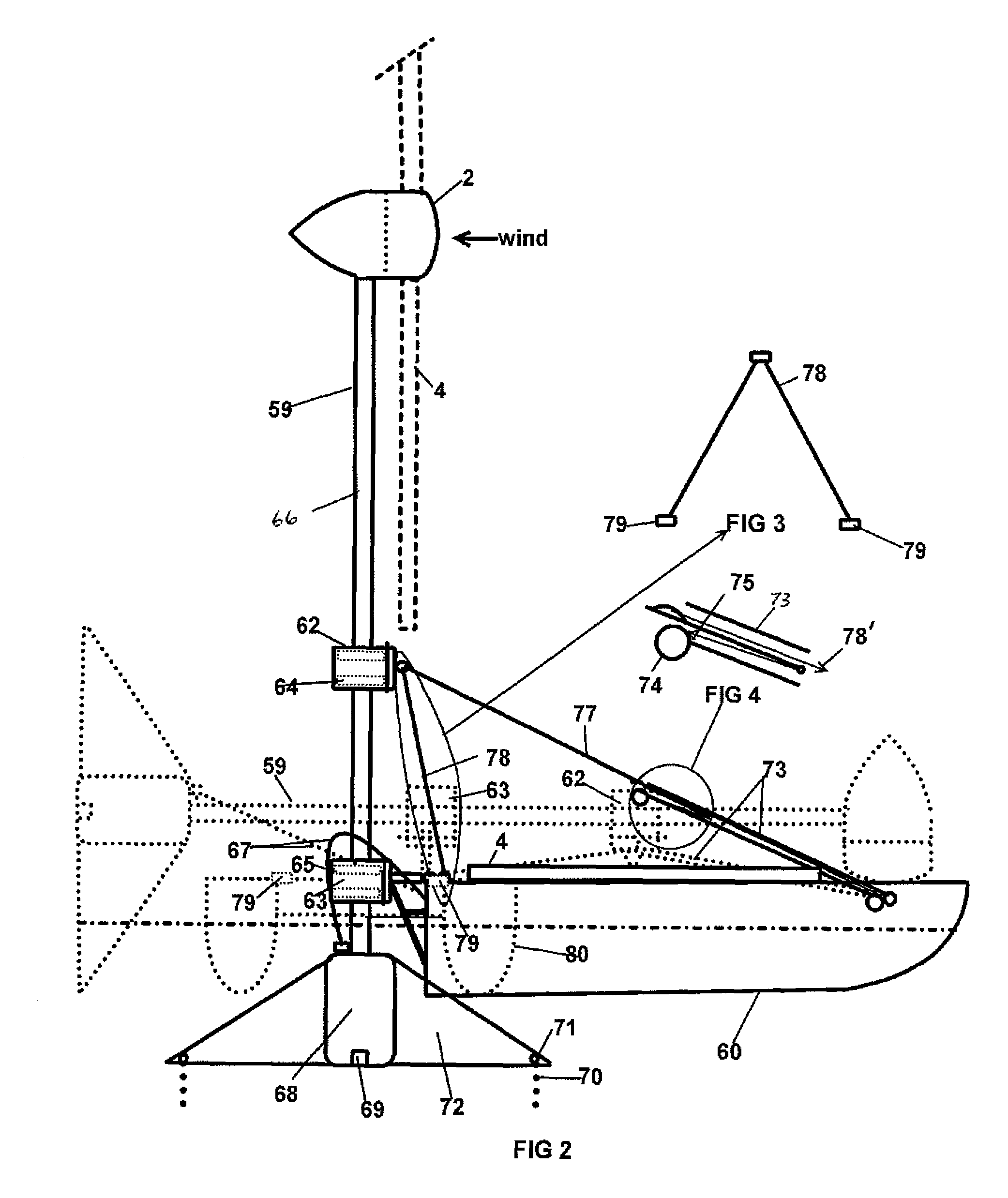
[0078]It will also be less costly to transport and mount this invention's much lighter weight turbine head and tower system than conventional technology, even on land. In the Great Plains area, for example, the hydraulic cylinder tip up system proposed in the second embodiment described above, for offshore can also work to advantage by eliminating the cumbersome crane and expensive road building projects. A heavy-duty transporter could transport turbines over rough terrain on its back without roads and tip it up and support it vertically with no crane needed. This would speed up the introduction of the 200,000 odd 5-MW wind turbines thought possible for this vast region. For example, at a turbine a day, 60 odd transporters could cover the Great Plains in 10 years for a connected capacity of 1 million MW.

[0079]For this invention's guy-wire supported tower, with both ends tapered, the weight savings are even more dramatic. This slimming down of the tower is also essential to minimize ...


PUM

PropertyMeasurementUnit
drag coefficientaaaaaaaaaa
weightaaaaaaaaaa
weightaaaaaaaaaa

Abstract

A method of deploying offshore wind turbine assemblies includes mounting a wind turbine assembly horizontally on a vessel and transporting the wind turbine assembly to an offshore site. The wind turbine assembly is raised to a vertical condition at the site and attached to anchor weights. Blades are attached to the turbine head after the wind turbine assembly is in the vertical condition. In one embodiment, the wind turbine assembly can include a tower including tapered lower and upper sections joined together at their respective wide ends, a turbine head connected to the upper section, and a platform connected to the lower section. The platform includes a buoy tank partially filled with ballast to provide mass and buoyancy. A wave piercing cowling is rotatively attached to the lower section. The turbine head can include an adjustable journal bearing, scabbard blade mounts, and a gearless induction generator with flux adjusting capabilities.

Description

CROSS REFERENCES TO RELATED APPLICATIONS[0001]This application claims the benefit of U.S. Provisional Application No. 61 / 197,170, filed Oct. 24, 2008, and U.S. Provisional Application No. 61 / 270,435, filed Jul. 8, 2009, which are hereby incorporated by reference.BACKGROUND OF THE INVENTION[0002]There is growing interest in using wind turbines as an alternative source of renewable energy with zero or nearly zero emissions. There is particular interest in locating wind turbines at offshore sites which generally have stronger, more persistent winds than onshore sites and are not located near residences or other human activities.[0003]The biggest problem today in achieving the promise of low cost electricity from the high capacity factor that is possible from offshore winds is the cost of deployment. For example, a new turbine and tower assembly can cost $1.5 million per MW onshore, but for offshore deployments, using monopile methods, even close to shore, will cost upwards of $2 millio...

Claims


Application Information

Patent Timeline
Patent Type & Authority Patents(United States)
IPC IPC(8): F03D11/04B23P21/00F01D25/00F01D25/16B63B35/44F03D1/00F03D7/02F03D11/00
CPCB63B35/44F03D7/0224B66C23/207F03D13/25F03D13/10F03D13/40B63B35/003F03D80/00B63B2009/067F05B2240/917F05B2240/93F05B2240/95F05B2260/20Y02E10/723Y02E10/727Y02E10/728Y02T50/675Y10S415/908Y10T29/49904Y02E10/726B63B2035/446F03D80/70Y02E10/72Y02T50/60B63B77/10
Inventor WEAVER, LLOYD E.
Owner WEAVER LLOYD E
Why Eureka
Try Eureka