Hydraulic apparatus

Inactive Publication Date: 2012-12-06
CETO IP
View PDF16 Cites 16 Cited by
  • Summary
  • Abstract
  • Description
  • Claims
  • Application Information

AI Technical Summary

Benefits of technology

[0010]It is an object of the present invention to overcome, or at least ameliorate, one or more of the def

Problems solved by technology

The need to design and manufacture such non-standard hardware means that it is difficult t

Method used


Image

  • Hydraulic apparatus
  • Hydraulic apparatus
  • Hydraulic apparatus

Examples


Embodiment Construction

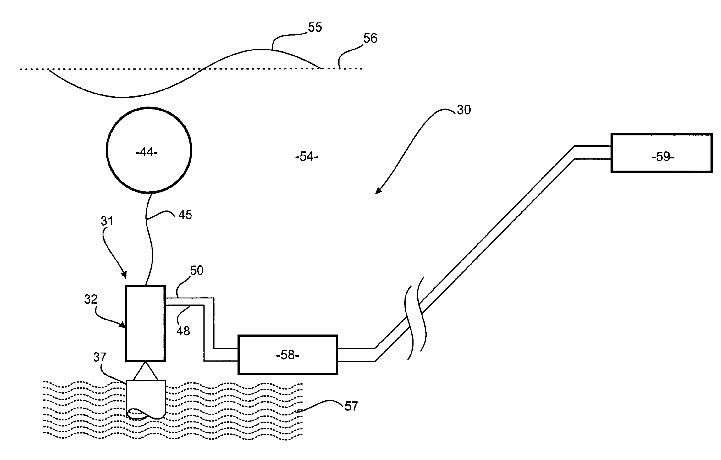
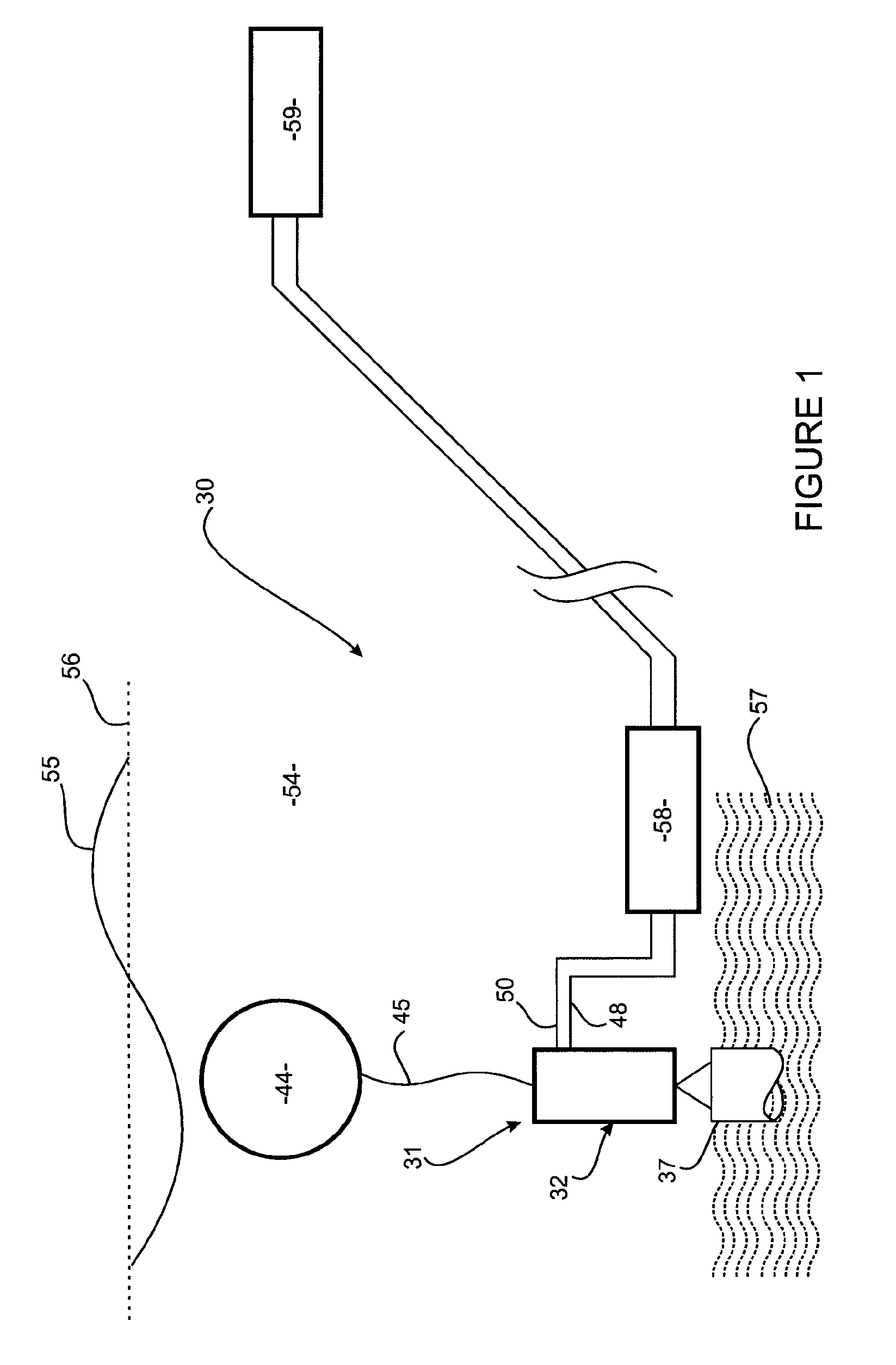
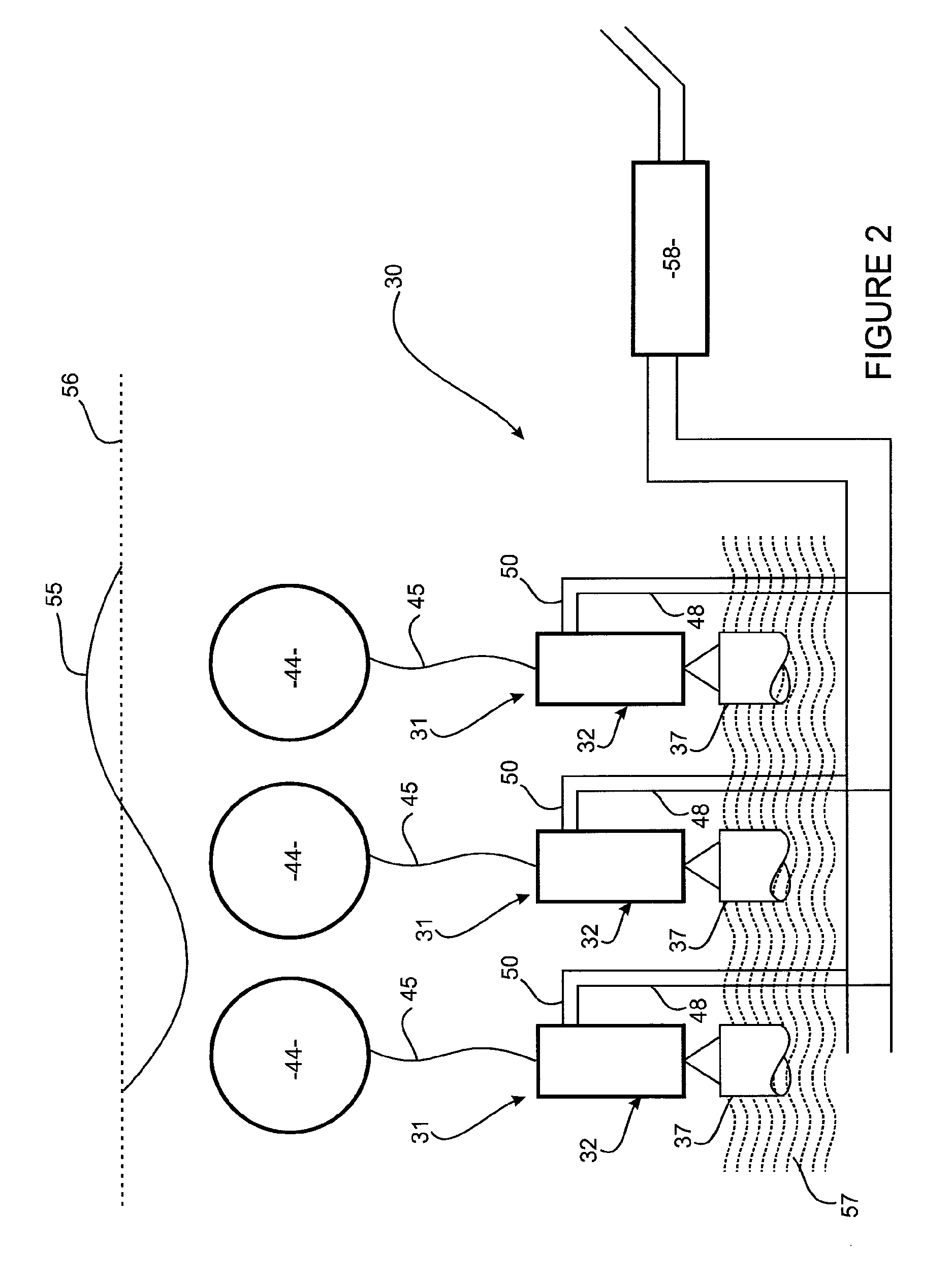
[0114]Referring to FIGS. 1 to 3, a closed loop hydraulic apparatus 30 for extracting energy from wave motion / converting wave energy includes an axial hydraulic pump 31 that includes a pump body 32 defining a chamber 33. The pump body 32 includes a side wall 34 having an upper end which is closed by a top, wall 35, and a lower end which is closed by a bottom wall 36. The bottom wall 36 is configured for attachment to a base 37.

[0115]A piston 38 is received by the chamber 33 such that the piston 38 partitions the chamber 33 into a rod or working side 39 and a blind side 40, and such that the piston 38 is able to slide back and forth within the chamber 33. A seal (not depicted) between the piston 38 and the side wall 34 inhibits fluid from flowing past the piston 38 and between the working side 39 and the blind side 40. Ideally, the working side 39 and the blind side 40 of the chamber 33 do not communicate within the pump 31 owing to the perfect sealing of the moving piston 38 with the...


PUM


Abstract

A closed-loop hydraulic apparatus 200 for converting wave energy comprises a pump 201 for pumping a fluid through the apparatus 200. The pump 201 includes a body 202 defining a chamber 203, and a piston 207 that partitions the chamber 203 into a working side 208 and a blind side 209. A buoyant actuator is connected to the piston 207. An inlet 64 is connected to the working side 208 of the chamber 203 so that the fluid is able to flow from the inlet 64 and into the working side 208 of the chamber 203. An outlet 63 is connected to the working side 208 of the chamber 203 so that the fluid is able to flow from the working side 208 of the chamber 203 to the outlet 63. A hydraulic controller 102 is operable to control the pump 201 by controlling the pressure of the fluid at the inlet 64 and the outlet 63 so as to optimise the output of the pump 201 in response to tidal variations and/or sea state. The pressure of the fluid at the inlet 64 and the outlet 63 is controlled in accordance with a control algorithm.

Description

FIELD OF THE INVENTION[0001]The present invention relates to hydraulic apparatus.[0002]Although the present invention will be described with particular reference to hydraulic apparatus for extracting energy from wave motion, it will be appreciated that the invention is applicable to other hydraulic apparatus.BACKGROUND ART[0003]Hydraulic apparatus for extracting energy from wave motion are known. Examples of such apparatus are disclosed in published International patent applications for CETO technology, PCT / AU2006 / 001187 and PCT / AU2007 / 001685 which are incorporated herein by reference.[0004]A prior art hydraulic apparatus for extracting energy from wave motion includes a base which is positioned on the seabed of a body of water. An axial hydraulic pump is mounted on the base such that the pump is able to pivot relative to the base. A piston rod of the pump is coupled to a buoyant actuator by a tether. Wave motion and the positive buoyancy of the buoyant actuator causes it to follow ...

Claims


Application Information

Patent Timeline
IPC IPC(8): F03B13/18F03B13/14
CPCF03B13/189Y02E10/38F05B2260/406F05B2240/40Y02E10/30F03B17/005F05B2240/95
Inventor ALLEN, GREG JOHNCALJOUW, RUUDFIEVEZ, JONATHAN PIERREKESSEL, DAVIDLAXTON, NIGELMANN, LAURENCE DREW
Owner CETO IP
Why Eureka
Try Eureka