Techniques for determining turbocharger speed

a technology of turbocharger and speed, which is applied in the direction of machines/engines, electric control, instruments, etc., can solve the problems achieve the effects of increasing engine torque and power, increasing intake air volume, and increasing engine efficiency and power outpu

Active Publication Date: 2006-02-16
CUMMINS INC
View PDF34 Cites 18 Cited by
  • Summary
  • Abstract
  • Description
  • Claims
  • Application Information

AI Technical Summary

Benefits of technology

[0002] Turbochargers are well known devices for pressurizing intake air entering the combustion chambers of an internal combustion engine to thereby increase the efficiency and power output of the engine. Generally, pressurizing the intake air increases the quantity of air entering the engine combustion chambers during intake, permitting more fuel to be utilized in establishing a fuel charge with a desired air-to-fuel ratio. Typically, increased engine torque and power results compared to a similar engine that is not turbocharged.
[0003] In a turbocharged engine, the exhaust manifold of the engine is in fluid communication with a rotatable turbine of the turbocharger via an exhaust conduit, and the exhaust gas flowing through this conduit causes the turbine to turn at a rate determined by exhaust gas pressure and flow rate. A compressor of the turbocharger is mechanically coupled to the turbine. The compressor is rotatably driven by the turbine as it turns. An inlet of the compressor receives fresh ambient air, and an outlet of the compressor is in fluid communication with an intake manifold of the engine via an intake conduit. The rotation of the compressor increases the amount of intake air supplied to the engine, which results in an increased pressure, often referred to as the “boost” pressure.

Problems solved by technology

Typically, increased engine torque and power results compared to a similar engine that is not turbocharged.

Method used


Image

  • Techniques for determining turbocharger speed
  • Techniques for determining turbocharger speed
  • Techniques for determining turbocharger speed

Examples


Embodiment Construction

[0016] For the purposes of promoting an understanding of the principles of the invention, reference will now be made to the embodiments illustrated in the drawings and specific language will be used to describe the same. It will nevertheless be understood that no limitation of the scope of the invention is thereby intended. Any alterations and further modifications in the described embodiments, and any further applications of the principles of the invention as described herein are contemplated as would normally occur to one skilled in the art to which the invention relates.

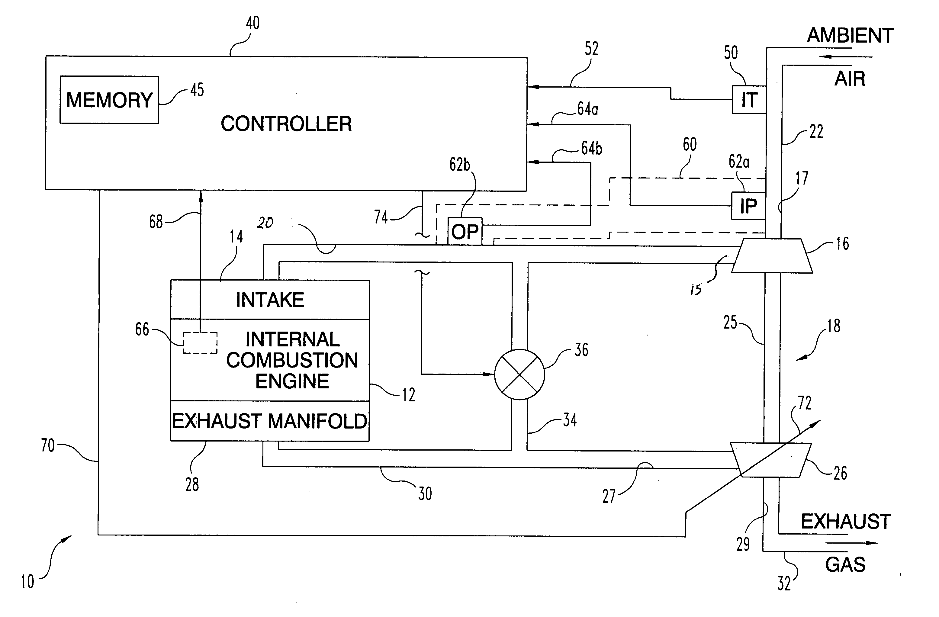
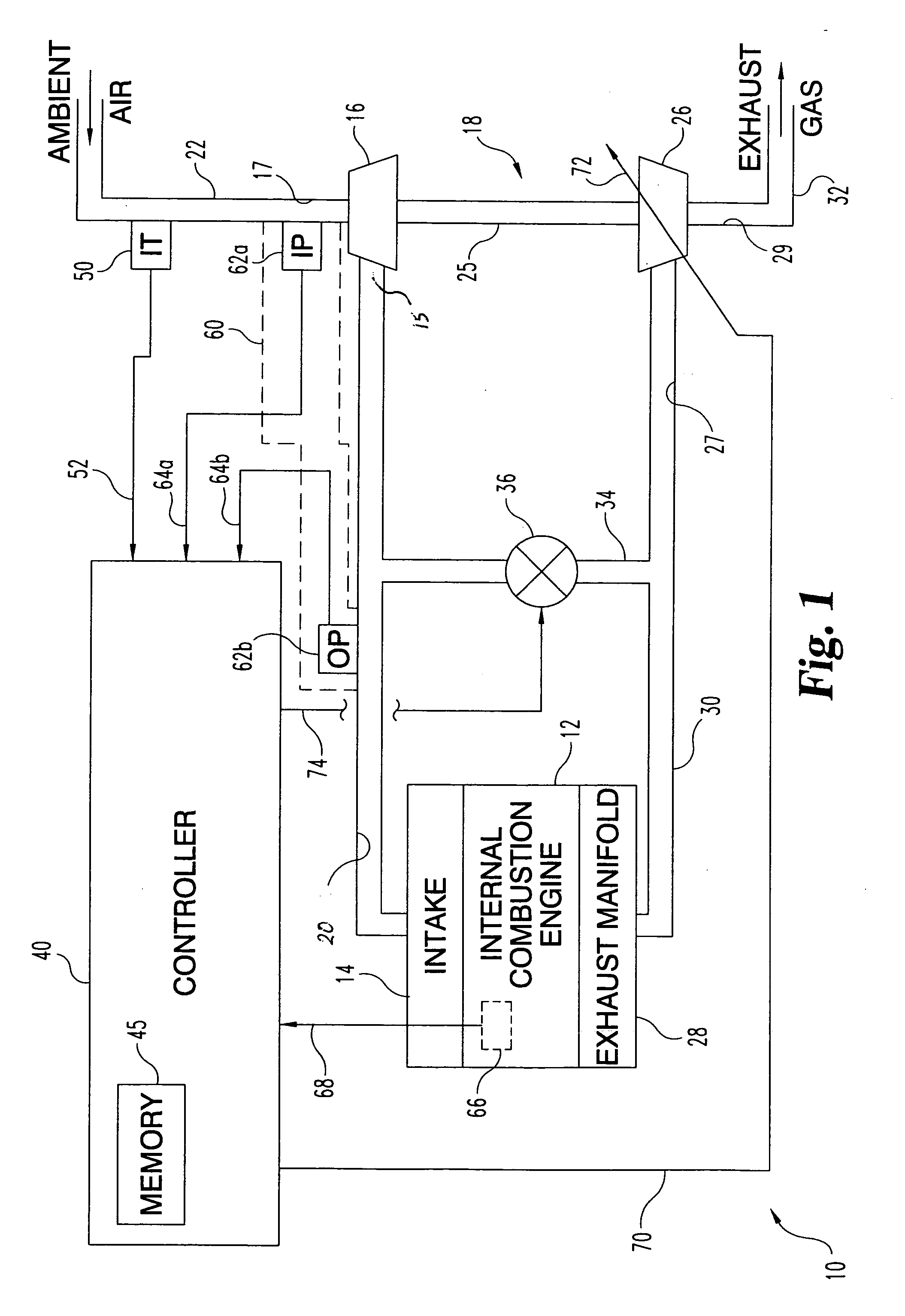
[0017] Referring now to FIG. 1, engine system 10 of one embodiment of the present invention is illustrated. System 10 includes internal combustion engine 12 and turbocharger 18. Turbocharger 18 includes compressor 16 and turbine 26. Engine 12 includes intake manifold 14 fluidly coupled to outlet 15 of compressor 16 via compressed air conduit 20. Compressor 16 includes compressor inlet 17 coupled to intake conduit...


PUM


Abstract

One embodiment of the present invention includes an internal combustion engine with a turbocharger. The turbocharger includes a compressor with an outlet coupled to an intake of the engine and a turbine coupled to an exhaust manifold of the engine. A a turbocharger speed estimate is determined from engine speed and a ratio between inlet and boost pressure for the compressor. The turbocharger speed estimate is further adjusted as a function of compressor boost pressure variation with time.

Description

BACKGROUND AND SUMMARY OF THE APPLICATION [0001] The present invention relates to internal combustion engines, and more particularly, but not exclusively, is relates to operation of an internal combustion engine with a turbocharger. [0002] Turbochargers are well known devices for pressurizing intake air entering the combustion chambers of an internal combustion engine to thereby increase the efficiency and power output of the engine. Generally, pressurizing the intake air increases the quantity of air entering the engine combustion chambers during intake, permitting more fuel to be utilized in establishing a fuel charge with a desired air-to-fuel ratio. Typically, increased engine torque and power results compared to a similar engine that is not turbocharged. [0003] In a turbocharged engine, the exhaust manifold of the engine is in fluid communication with a rotatable turbine of the turbocharger via an exhaust conduit, and the exhaust gas flowing through this conduit causes the turb...

Claims


Application Information

Patent Timeline
Patent Type & Authority Applications(United States)
IPC IPC(8): F02D23/00F02B33/44
CPCF02B37/22F02D23/00F02D41/0007Y02T10/144F02D2200/0414F02M25/0707F02M25/0727F02D2200/0406F02M26/05F02M26/23Y02T10/12
Inventor AKINS, MARK D.KING, DENNISSLATER, TODDMILBURN, BRYANPATAKY, GREG
Owner CUMMINS INC
Why Eureka
Try Eureka