Switch cabinet and incoming and outgoing line function module thereof

A technology of functional modules and incoming and outgoing lines, which is applied in the direction of switchgear components, vertical pull and isolated switchgear, etc., can solve the problems of inability to realize integrated assembly, achieve convenient and fast assembly, improve production efficiency, and reduce occupied space.

CN103683070AInactive Publication Date: 2014-03-26STATE GRID CORP OF CHINA +1
6 Cites 7 Cited by

Patent Information

Authority / Receiving Office
CN · China
Current Assignee / Owner
Publication Date
2014-03-26
Estimated Expiration
Not applicable · inactive patent

Smart Images

  • Figure 1
    Figure 1
  • Figure 2
    Figure 2
  • Figure 3
    Figure 3
Patent Text Reader

Abstract

The invention discloses a switch cabinet and an incoming and outgoing line function module thereof. The incoming and outgoing line function module comprises a conducting core with an axis extending linearly and a core-penetrating type mutual inductor sleeved on the periphery of the conducting core, the front end and the rear end of the conducting core are respectively provided with a first connection structure and a second connection structure which are serially connected on a main loop of the switch cabinet, the conducting core and the mutual inductor are solidified into a whole through an insulator casted on the outsides thereof, and the surface of the insulator is provided with adaptation holes which are corresponding to the first connection structure and second connection structure respectively and used for leading in an external conductor for conducting electricity and leading out an external conductor for conducting electricity. The core-penetrating type mutual inductor with the conducting core penetrating from the center is adopted in the incoming and outgoing line function module, and is casted into a whole through epoxy resin to form the incoming and outgoing line function module with a CT, space of a cabinet body is effectively utilized by the arrangement, and height of the cabinet body is decreased.
Need to check novelty before this filing date? Find Prior Art

Description

technical field

[0001] The invention relates to a power transmission and distribution switchgear. Background technique

[0002] The middle-mounted switchgear structure in the prior art is such as a switchgear disclosed in CN 203260933 U. The cabinet body is divided into multiple compartments by wall plates made of steel plates, generally including the busbar room on the top and the circuit breaker room in the middle. , The cable room at the bottom, and the circuit breaker room is equipped with a handcart circuit breaker. The handcart circuit breaker includes a handcart that moves left and right and is assembled on the guide rail in the horizontal direction and a circuit breaker fixed on the handcart. The circuit breaker A set of static contacts whose axis is along the horizontal direction is fixed on the wall plate between the cable room and the circuit breaker correspondingly. Arresters, grounding switches, and primary outgoing cables are connected in rows. Since the outl...

Examples

Embodiment Construction

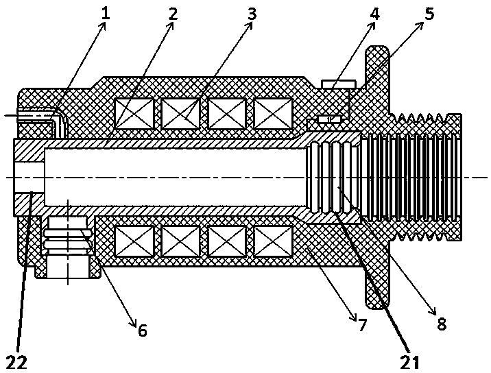
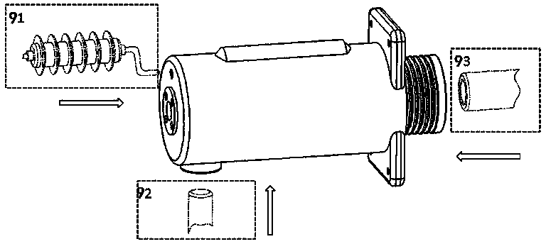
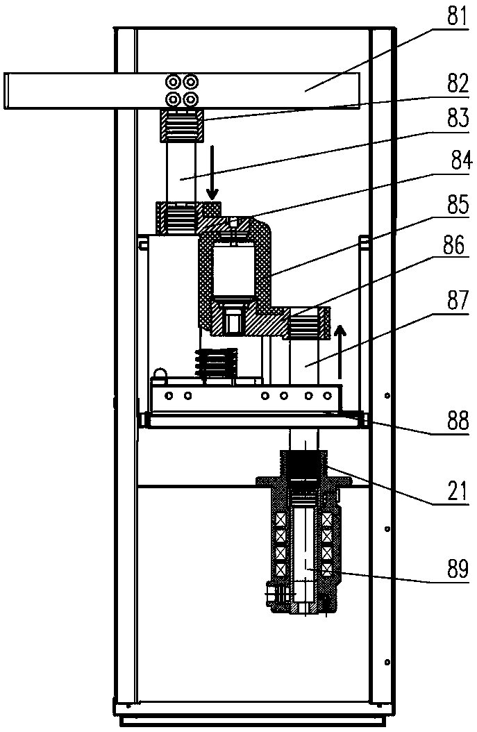
[0020] Such as figure 1 , figure 2 As shown, the embodiment of the incoming and outgoing line functional module of the present invention includes a conductive core 2 whose tubular axis extends in a straight line and a through-type transformer 3 sleeved on the periphery of the conductive core 2. The front and rear two sides of the conductive core 2 The ends are respectively provided with a first wiring structure 21 and a second wiring structure 22 for connecting in series to the main circuit of the switch cabinet. The outer circumference of the conductive core 2 is fixedly connected with the grounding switch interface 6 and the lightning arrester interface 1. The grounding switch interface 6 and the lightning arrester interface 1 are located on the rear side of the transformer 3. The conductive core 2 is also connected with a live display sensor 5 and a junction box 4 through wires. . The junction box 4 is fixed on the outer periphery of the cylinder, and the charging displa...