Biomass-oil catalytic hydrogenation reaction device and catalytic hydrogenation method thereof

A technology of catalytic hydrogenation and biomass oil, which is applied in the fields of chemical engineering and energy engineering, to achieve the effects of catalytic hydrogenation reaction, catalyst regeneration, and increased hydrogen dissolution

Active Publication Date: 2015-06-17
SOUTHEAST UNIV
View PDF4 Cites 3 Cited by
  • Summary
  • Abstract
  • Description
  • Claims
  • Application Information

AI Technical Summary

Problems solved by technology

[0010] Purpose of the invention: In order to overcome the deficiencies in the prior art, the present invention provides a biomass oil catalytic hydrogenation reaction device and its catalytic hydrogenation method, which solves the problem of temperature control in the catalytic hydrogenation reaction process, the problem of removing heat and Timely Regeneration of Deactivated Catalysts

Method used


Image

  • Biomass-oil catalytic hydrogenation reaction device and catalytic hydrogenation method thereof

Examples


Embodiment Construction

[0017] The present invention will be further described below in conjunction with the accompanying drawings.

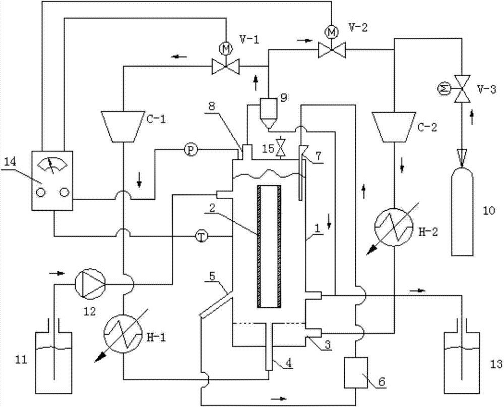
[0018] Such as figure 1 As shown, a biomass oil catalytic hydrogenation device includes a reaction tower 1, a riser 2 fixed in the inner cavity of the reaction tower 1 through a bracket, a temperature sensing probe set in the inner cavity of the reaction tower 1, and a 1 Pressure-sensitive probe in the inner cavity, catalyst regeneration device 6, gas-liquid separator 9, hydrogen source 10, biomass crude oil storage tank 11, oil delivery pump 12, refined oil storage tank 13, flow control device 14, first solenoid valve V-1, second solenoid valve V-2, third solenoid valve V-3, first compressor C-1, second compressor C-2, first heat exchanger H-1 and second heat exchanger H-2.

[0019] The top of the reaction tower 1 is provided with a catalyst inlet 7, a reaction gas outlet 8 and an exhaust valve 15, and the exhaust valve 15 is used to discharge miscellaneous gases su...


PUM


Abstract

The invention discloses a biomass-oil catalytic hydrogenation reaction device. The biomass-oil catalytic hydrogenation reaction device comprises a reaction tower, a lift pipe fixed in the inner cavity of the reaction tower through a support, a temperature sensing probe arranged in the inner cavity of the reaction tower, a catalyst reactivation device, a gas-liquid separator, a hydrogen source, a biomass crude oil storage tank, an oil transfer pump, a refined oil product storage tank, a flow control device, a first electromagnetic valve, a second electromagnetic valve, a third electromagnetic valve, a first compressor, a second compressor, a first heat exchanger and a second heat exchanger. The invention also discloses a catalytic hydrogenation method of the biomass-oil catalytic hydrogenation reaction device, wherein the catalytic hydrogenation method comprises the steps of cooling hydrogen circulation, reactive hydrogen circulation, a catalyst reactivation circulation, and regulation and control on biomass oil channel and hydrogen flow. The biomass-oil catalytic hydrogenation reaction device solves the temperature control problem in the catalytic hydrogenation reaction, the heat dissipation problem and the immediate reactivation problem of the deactivated catalyst.

Description

technical field [0001] The invention relates to a biomass oil catalytic hydrogenation reaction device and a catalytic hydrogenation method thereof, belonging to the fields of energy engineering and chemical engineering. Background technique [0002] As a renewable energy source, biomass can replace petroleum resources to produce liquid fuels and chemicals. Biomass oil is a liquid fuel produced from biomass through fast pyrolysis technology. Biomass oil has a high oxygen content, which makes it poor in thermal stability and low in calorific value. It must be upgraded and modified before it can be converted into high-grade fuel. [0003] Catalytic hydrogenation is a good method in biomass oil upgrading technology. Because it can significantly reduce the oxygen content of biomass oil and increase the energy density, it has attracted extensive attention. [0004] In the process of catalytic hydrogenation of biomass oil, polymerization reaction is easy to occur at high tempera...

Claims


Application Information

Patent Timeline
Patent Type & Authority Patents(China)
IPC IPC(8): C10G3/00
CPCY02P30/20
Inventor 徐惠斌钟文琪金保昇
Owner SOUTHEAST UNIV
Why Eureka
Try Eureka