Paper sheet handling device with transport unit

A paper processing and conveying unit technology, which is applied to coin accepting devices, thin material processing, transportation and packaging, etc., can solve the problems of blockage of the distribution door, inconvenient use, and difficulty in changing the direction of incoming and outgoing payments, so as to suppress blockage. Effect

Active Publication Date: 2014-05-07
HITACHI OMRON TERMINAL SOLUTIONS CORP
View PDF9 Cites 7 Cited by
  • Summary
  • Abstract
  • Description
  • Claims
  • Application Information

AI Technical Summary

Problems solved by technology

Problems here are, for example, jams caused by banknotes colliding with the distributing gate arranged in the conveying path, or failures in the next payment transaction caused by accumulation defects in the storage section, rejections caused by unidentifiable currency types, authenticity, etc.
In addition, when a foreign object such as a coin is caught in the banknote bundle, it is conveyed to the storage unit together with the banknote, and as a result, there is also a problem that it becomes a cause of clogging in the device.
And, in the case of inserting banknotes into the pocket-type deposit and withdrawal port in the deposit and withdrawal port arranged approximately vertically like the device of Patent Document 2, the user inserts his hand into the depth of the deposit and withdrawal port at the timing of issuing and receiving the bills. necessary, so there is such a problem that it is inconvenient to use
Moreover, the device of Patent Document 3 has the problem that it cannot be used in a recirculating banknote processing device because it can only deposit money.
Moreover, if the cash deposit machine that makes the banknotes into the vertical position and the automatic teller machine that discharges the banknotes horizontally as in cited document 3 are arranged, then there is a problem that the operability decreases.
[0008] On the other hand, as another subject, in the past, depending on the place where the automatic teller machine is used, there have been various needs for the banknote deposit and withdrawal directions of the paper processing device. paper processing device, there is a problem that the manufacturing cost of the paper processing device increases
Moreover, it is not easy to change the deposit and withdrawal direction for the existing cash processing device

Method used


Image

  • Paper sheet handling device with transport unit
  • Paper sheet handling device with transport unit
  • Paper sheet handling device with transport unit

Examples


no. 1 Embodiment

[0039] A-1. The general structure of the automatic cash transaction device 550 with the conveying unit:

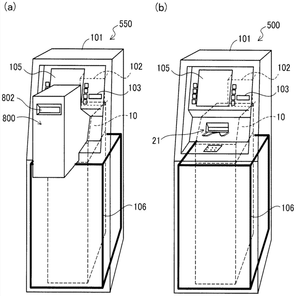
[0040] figure 1 It is an explanatory drawing for demonstrating the schematic structure of the automatic teller machine with unit 550 of 1st Example. figure 1 (a) shows an example of the automatic teller machine 550 with a unit. figure 1(b) illustrates the automatic teller machine 500 as an example. The automatic teller machine with unit 550 is a device for performing transactions such as depositing and withdrawing cash (banknotes), and remittance, and has a structure in which the automatic teller machine 500 is equipped with the transport unit 800 . The transport unit 800 transports the banknotes inserted into the unit-side deposit and withdrawal port 802 to the deposit and withdrawal port 21 , and transports the banknotes discharged from the deposit and withdrawal port 21 to the unit-side deposit and withdrawal port 802 . The specific structure of the transport unit 80...

Deformed example 1

[0131] In the first embodiment, a pair of clamping mechanisms 402, 403 and a pair of pressure plates 202, 203 are arranged overlapping (refer to Figure 5 ), but it can also be replaced by a structure in which a pair of clamping mechanisms 402, 403 and a pair of pressing plates 202, 203 do not overlap. For example, the pair of clamping mechanisms 402 and 403 may be disposed above the pair of pressure plates 202 and 203 (on the side closer to the deposit and withdrawal port 21 ). In this case, the pair of clamping mechanisms 402 , 403 does not overlap the pair of pressure plates 202 , 203 . Even if it is such a structure, the same effect as the automatic teller machine 550 with a unit of 1st Example can be acquired. That is, even in this case, when the banknote Ca is dropped into the banknote storage area Ra through the deposit and withdrawal port 21 from the banknote transfer portion 803, the rear side clamping mechanism 402 is moved toward the banknote storage area Ra side b...

Deformed example 2

[0133] The first example illustrates the like Figure 12 to Figure 15 As shown, when the banknote Ca is deposited, the front side holding mechanism 403 is in a state of being substantially aligned with the front side pressing plate 203 on the side of the banknote storage area Ra, and the rear side holding mechanism 402 is protruding relative to the rear side pressing plate 202. An example of the state on the banknote storage area Ra side, but the positional relationship between the pair of clamping mechanisms 402, 403 and the pair of pressure plates 202, 203 at the time of deposit is not limited to the above relationship. The positional relationship between the pair of clamping mechanisms 402, 403 and the pair of pressing plates 202, 203 when depositing money is as long as at least one of the pair of clamping mechanisms 402, 403 protrudes into the banknote storage area more than one of the pair of pressing plates 202, 203 On the Ra side, an arbitrary structure can be employed....


PUM


Abstract

The objective of the present invention is to provide technology for simply creating a paper sheet handling device having various deposit directions. A paper sheet handling device with transport unit is provided. The paper sheet handling device is provided with an inlet/outlet; a pair of plate-shaped members configuring a space portion capable of housing paper sheets therebetween; a pair of clamping mechanisms configured so that the distance from each to the other is variable, and which are capable of clamping and transporting a paper sheet, which has been inserted into the space portion, by movement; and a control unit which is capable of controlling operation of the pair of clamping mechanisms. The transport unit is disposed at the top of the inlet/outlet, and is provided with: a paper sheet transfer unit for performing transfer of a paper sheet between the unit-side inlet/outlet and the paper sheet handling device; and a paper sheet transport path for transporting the paper sheet. The control unit, when a paper sheet is inserted from the paper sheet transfer unit into the space portion, projects at least one clamp mechanism to the side that is more to the space portion than to the plate-shaped member.

Description

technical field [0001] The invention relates to a sheet processing device with a conveying unit. Background technique [0002] A banknote handling device that handles banknotes, receipts, and the like is installed in automatic teller machines used by financial institutions and the like. This banknote handling device is constituted by combining various units. Such units include: deposit and withdrawal mechanism, equipped with a deposit and withdrawal port; banknote identification department; banknote conveying path; temporary storage warehouse, temporarily storing banknotes; Banknotes; Recycling warehouse, to store and send out banknotes for both deposit and withdrawal in succession; Rejection warehouse, to store deposit banknotes that have not been stored in the deposit warehouse or circulation warehouse, or banknotes that have not been paid out of the banknotes that have been successively sent out from the withdrawal warehouse; As well as the loading and recycling warehou...

Claims


Application Information

Patent Timeline
Patent Type & Authority Applications(China)
IPC IPC(8): G07D11/00
CPCB65H31/3027B65H83/02B65H2301/4213B65H2301/42142G07D11/14
Inventor 三轮真也藤田准司上野正康鱼住敦子笹岛洋太
Owner HITACHI OMRON TERMINAL SOLUTIONS CORP
Why Eureka
Try Eureka