Paper handling device with conveyor unit
A paper processing and conveying unit technology, which is applied in coin accepting devices, thin material processing, transportation and packaging, etc., can solve the problems of distributing door blocking, decreased operability, inconvenient use, etc., and achieve the effect of suppressing blocking
- Summary
- Abstract
- Description
- Claims
- Application Information
AI Technical Summary
Problems solved by technology
Method used
Image
Examples
no. 1 Embodiment
[0039] A-1. The general structure of the automatic cash transaction device 550 with the conveying unit:
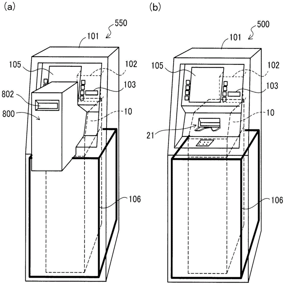
[0040] figure 1 It is an explanatory drawing for demonstrating the schematic structure of the automatic teller machine with unit 550 of 1st Example. figure 1 (a) shows an example of the automatic teller machine 550 with a unit. figure 1(b) illustrates the automatic teller machine 500 as an example. The automatic teller machine with unit 550 is a device for performing transactions such as depositing and withdrawing cash (banknotes), and remittance, and has a structure in which the automatic teller machine 500 is equipped with the transport unit 800 . The transport unit 800 transports the banknotes inserted into the unit-side deposit and withdrawal port 802 to the deposit and withdrawal port 21 , and transports the banknotes discharged from the deposit and withdrawal port 21 to the unit-side deposit and withdrawal port 802 . The specific structure of the transport unit 80...
Deformed example 1
[0131] In the first embodiment, a pair of clamping mechanisms 402, 403 and a pair of pressure plates 202, 203 are arranged overlapping (refer to Figure 5 ), but it can also be replaced by a structure in which a pair of clamping mechanisms 402, 403 and a pair of pressing plates 202, 203 do not overlap. For example, the pair of clamping mechanisms 402 and 403 may be disposed above the pair of pressure plates 202 and 203 (on the side closer to the deposit and withdrawal port 21 ). In this case, the pair of clamping mechanisms 402 , 403 does not overlap the pair of pressure plates 202 , 203 . Even if it is such a structure, the same effect as the automatic teller machine 550 with a unit of 1st Example can be acquired. That is, even in this case, when the banknote Ca is dropped into the banknote storage area Ra through the deposit and withdrawal port 21 from the banknote transfer portion 803, the rear side clamping mechanism 402 is moved toward the banknote storage area Ra side b...
Deformed example 2
[0133] The first example illustrates the like Figure 12 to Figure 15 As shown, when the banknote Ca is deposited, the front side holding mechanism 403 is in a state of being substantially aligned with the front side pressing plate 203 on the side of the banknote storage area Ra, and the rear side holding mechanism 402 is protruding relative to the rear side pressing plate 202. An example of the state on the banknote storage area Ra side, but the positional relationship between the pair of clamping mechanisms 402, 403 and the pair of pressure plates 202, 203 at the time of deposit is not limited to the above relationship. The positional relationship between the pair of clamping mechanisms 402, 403 and the pair of pressing plates 202, 203 when depositing money is as long as at least one of the pair of clamping mechanisms 402, 403 protrudes into the banknote storage area more than one of the pair of pressing plates 202, 203 On the Ra side, an arbitrary structure can be employed....
PUM
 Abstract
Description
Claims
Application Information
 - R&D
- Intellectual Property
- Life Sciences
- Materials
- Tech Scout
- Unparalleled Data Quality
- Higher Quality Content
- 60% Fewer Hallucinations
Browse by: Latest US Patents, China's latest patents, Technical Efficacy Thesaurus, Application Domain, Technology Topic, Popular Technical Reports.
© 2025 PatSnap. All rights reserved.Legal|Privacy policy|Modern Slavery Act Transparency Statement|Sitemap|About US| Contact US: help@patsnap.com


