
Electric agricultural brush cutter
A brush cutter, electric technology, applied in the field of electric agricultural brush cutter, can solve the problems of long time required, not neat cutting, poor adaptability of pasture, etc., and achieve the effect of reducing labor intensity, cutting neatly and working conveniently
- Summary
- Abstract
- Description
- Claims
- Application Information
AI Technical Summary
Problems solved by technology
Method used
Image

Examples
Embodiment Construction
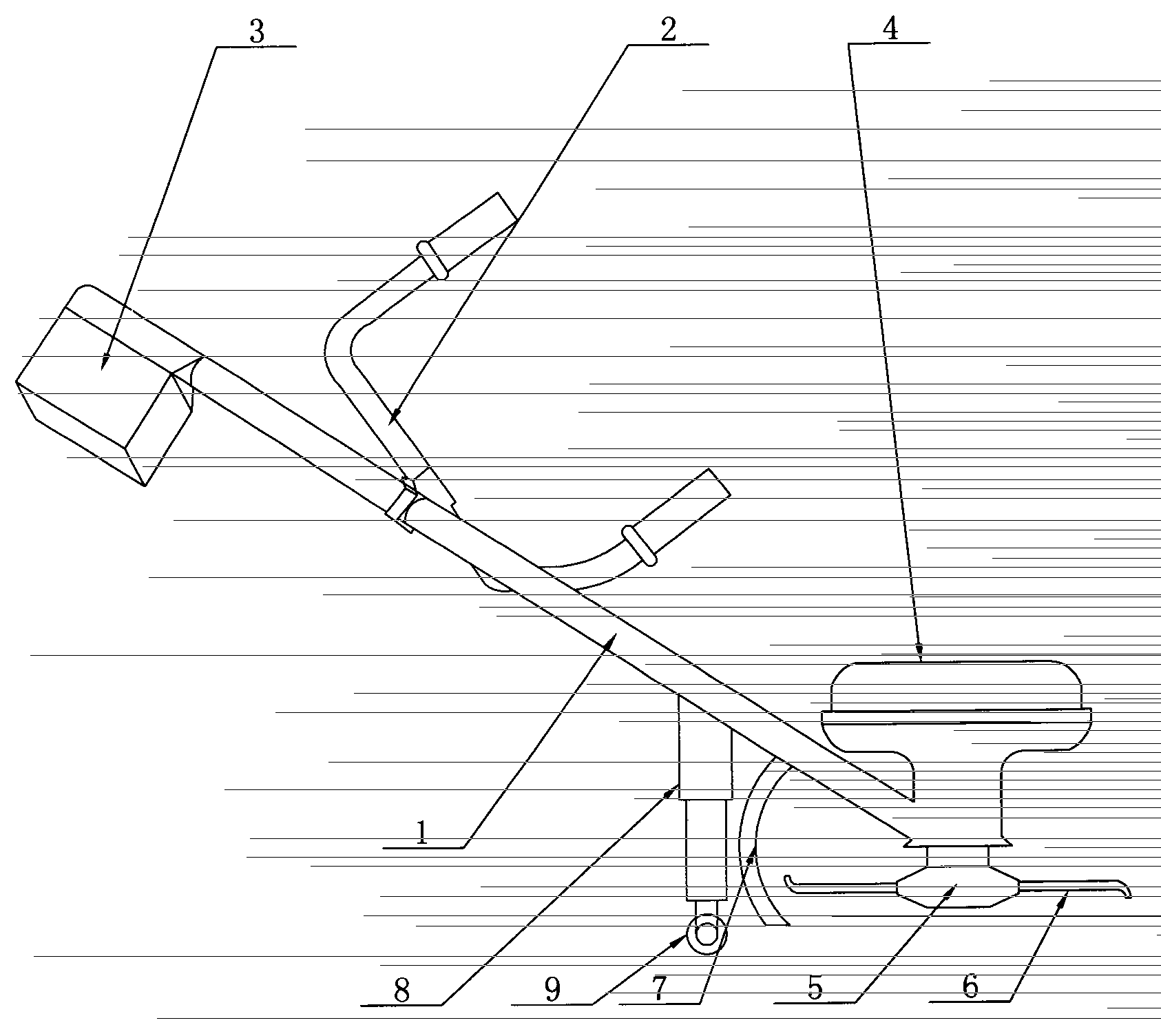
[0011] see figure 1 , the specific embodiment adopts the following technical scheme: it includes operating lever 1, handle 2, battery box 3, motor 4, cutter head 5, blade 6, shield 7, operating lever 1 is equipped with handle 2, battery box 3 is installed On the upper end of the operating rod 1, the motor 4 is installed at the lower end of the operating rod 1, the motor 4 is connected with the cutter head 5, the blade 6 is installed on the cutter head 5, and a shield 7 is installed on one side of the operating rod 1, which also includes a support Frame 8, roller 9, bracing frame 8 is installed on one side of operating rod 1 and the outside of shield 7, and the lower end of bracing frame 8 is equipped with roller 9.
[0012] Described support frame 8 is electric lifting support frame.
[0013] In this specific embodiment, the operating rod 1 is supported by the support rod 8 to reduce labor intensity, while ensuring that the blades 6 are at the same height, so that the cutting...
PUM
 Abstract
Description
Claims
Application Information