Dual chain hoist arrangement

a chain hoist and chain hoist technology, applied in the direction of hoisting equipment, trolleys, load-engaging elements, etc., can solve the problems of residual length, fixed spacing between the hooks that may be excessively small or excessively large, and the need to replace the lifting beam with a new one. achieve the effect of reducing the torqu

Inactive Publication Date: 2010-07-22
STAHL CRANESYSTEMS GMBH
View PDF4 Cites 5 Cited by
  • Summary
  • Abstract
  • Description
  • Claims
  • Application Information

AI Technical Summary

Benefits of technology

[0011]Since the two lifting beam sections can be telescopically adjusted, the hook blocks can be moved toward or away from one another depending on the given application. Consequently, it is possible to adjust any hook spacing within the possible adjusting range. This adjustment is effected by setting the second chain wheel group in rotation. This causes the two lifting beam sections to move relative to one another. The second load chain simultaneously is effectively shortened in accordance with the telescoping movement. Consequently, the second chain wheel group forms as it were, a virtual anchor for the second load chain that takes up or pays out the chain in accordance with the adjustment in order to maintain the second hook block at the same height as prior to the adjustment regardless of the adjustment of this second hook block. Both hook blocks usually remain at the same height. In certain applications, however, it may also be reasonable to adjust the heights relative to one another, wherein this height adjustment is not influenced by the adjustment of the lifting beam width.

Problems solved by technology

This method is widely used, but has the disadvantage that the lifting beam must be replaced with another lifting beam when the dimensions of the load change.
The disadvantage of such chain hoists is the fixed spacing between the hooks that may be excessively small or excessively large.
Another disadvantage of such dual chain hoists results from the residual length, i.e., the smallest distance that the hooks can be from a building or wall when the dual chain hoist is moved in the direction of the wall.

Method used


Image

  • Dual chain hoist arrangement
  • Dual chain hoist arrangement
  • Dual chain hoist arrangement

Examples


Embodiment Construction

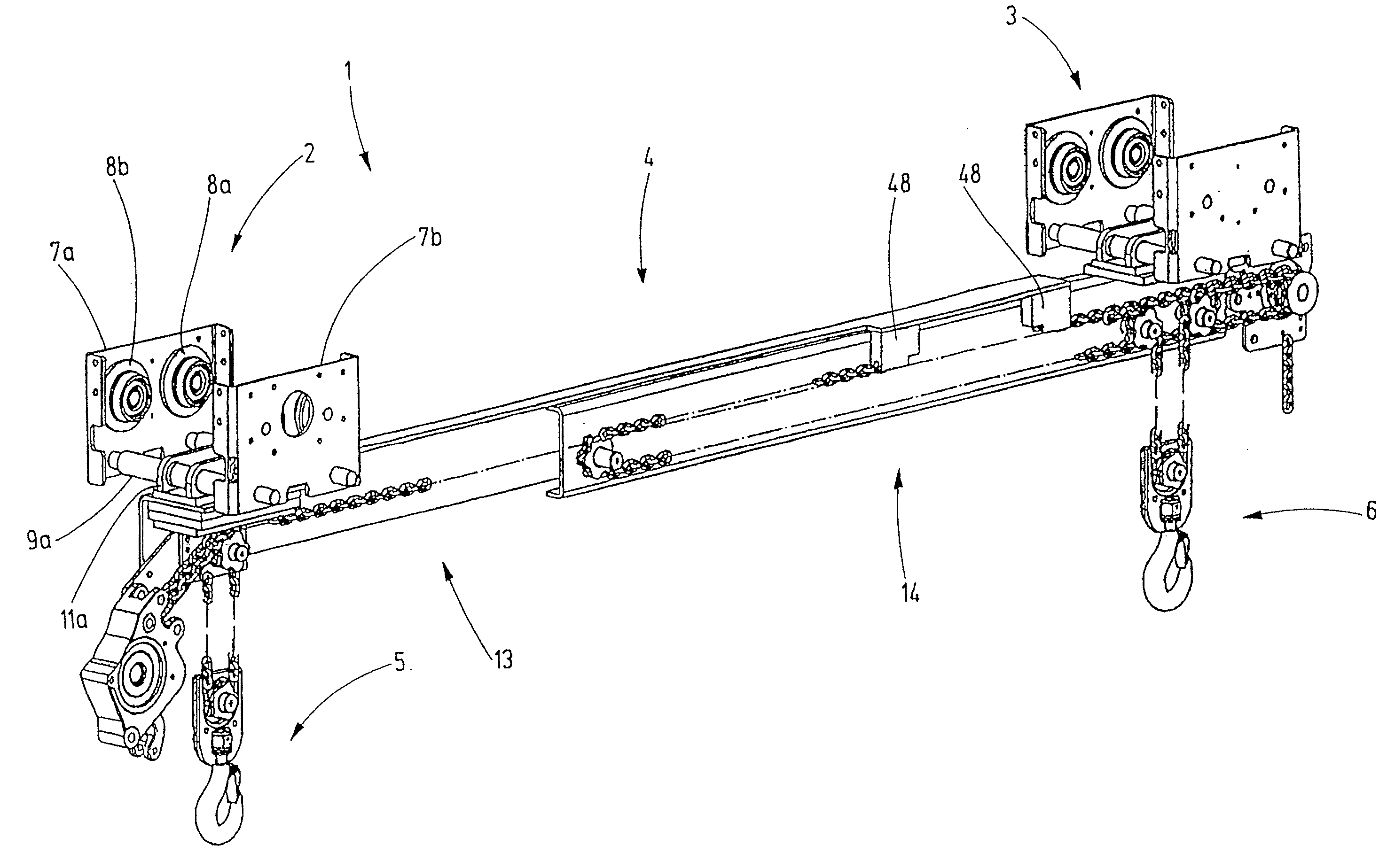
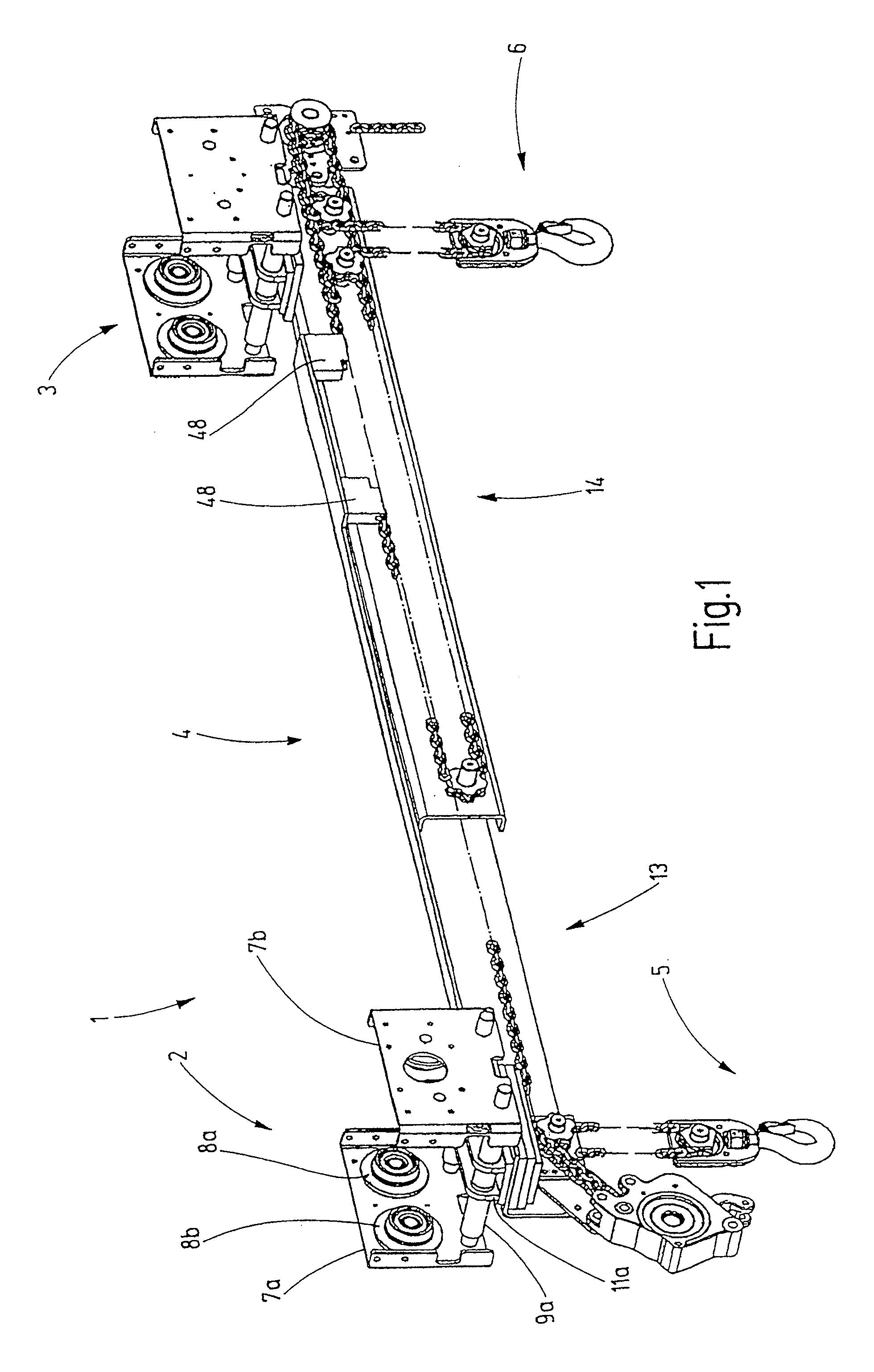
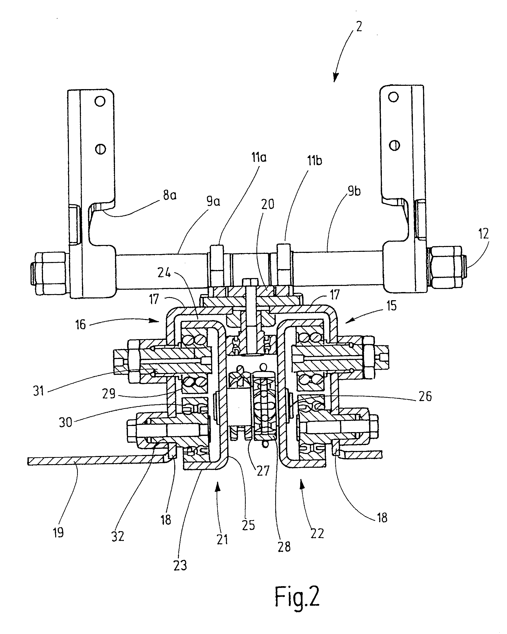
[0024]Referring now more particularly to the drawings, there is shown an illustrative dual chain hoist 1 in accordance with the invention, which basically comprises two propelling mechanisms 2,3, a length adjustable lifting beam 4, and two hook blocks 5,6 mounted in depending fashion from opposite ends of the adjustable lifting beam 4. The illustrated propelling mechanisms 2 includes two trolley side cheeks 7a,7b that are aligned parallel to one another. The trolley side cheek 7a carries two rotatably supported flanged wheels 8a,8b, and corresponding flanged wheels are provided on the opposite inner side of the trolley side cheek 7b in the form of a mirror image relative to the flanged wheels 8a and 8b.

[0025]Through-bolts 12 are used for screwing the two trolley side cheeks 7a,7b to corresponding brackets 11a,11b with spacer elements 9a,9b therebetween. On each propelling mechanism, the two side cheeks 7a,7b are mounted on the respective lifting beam 13,14 with two sets of spacer e...


PUM


Abstract

A dual chain hoist having a lifting beam that can be telescopically extended and contracted, wherein load chains respectively extend to hook blocks suspended beneath the lifting beam in the vicinity of the ends of two telescoping sections that form the lifting beam. The distance between the telescoping sections can be varied with another chain. The chain for varying the length of the lifting beam extends over a chain wheel that is connected without rotational play to another chain wheel from which the load chain of the hook block of the respective telescoping lifting beam section.

Description

CROSS-REFERENCE TO RELATED APPLICATIONS[0001]This patent application claims the benefit of German Patent Application No. 10 2009 005 592.4, filed Jan. 21, 2009.FIELD OF THE INVENTION[0002]The present invention relates generally to chain hoists, and more particularly, to a dual chain hoist having a lifting beam for supporting loads.BACKGROUND OF THE INVENTION[0003]Projecting loads or loads that tend to buckle cannot be hoisted with a single hook and belts. Such loads require the attachment of a lifting beam, from which the belts or other load suspension means are suspended in order to attach the load. This method is widely used, but has the disadvantage that the lifting beam must be replaced with another lifting beam when the dimensions of the load change.[0004]Alternatively, it is also known to utilize chain hoists in the form of so-called dual chain hoists, in which two chain hoists are suspended from a lifting beam. These two chain hoists are usually actuated by a single drive mot...

Claims


Application Information

Patent Timeline
Patent Type & Authority Applications(United States)
IPC IPC(8): B66C1/34B66C1/10
CPCB66C11/06B66C17/04B66C11/16
Inventor KASPER, JURGENKITTSTEINER, PETER
Owner STAHL CRANESYSTEMS GMBH
Why Eureka
Try Eureka